Toyota 2.4L/22RE Air Flow Meter (AFM)
Visitor # since 18.MAY.2002

Contents:
Return to the main Cheap Tricks page...
Introduction
The Toyota 22R-E engine is electronically fuel injected. As such they lack a mechanical carburetor and instead split the function of the carburetor into three parts, namely the Air Flow Meter (AFM) or Volume Air Flow (VAF) meter in the air cleaner box, the throttle body and the fuel injector. The air flow meter uses a flapper vane and temperature sensor to detect the amount and temperature of the incoming air flow. The throttle body controls the air flow into the engine and the fuel injectors supply the proper amount of fuel to each piston depending upon operating conditions.
Note that this type of air flow sensor measures the volume of the incoming air. This is different than later Mass Air Flow (MAF) sensors that measure the mass of the incoming air flow.
While this information is based upon the AFM system in the 22R-E engine, most of it applies to other Toyota EFI engines. For specific information, be sure to consult the service manual for your model engine. On the 22RE engine, the AFM is located atop the air filter box. In a stock engine compartment, this is in the driver's side front corner. In the image below, the AFM is dead center in the image:
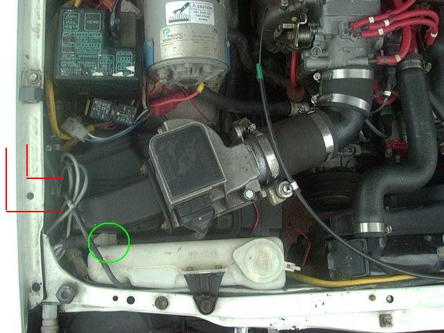 |
| Air Flow Meter location |
[Back to the top]
Theory of Operation:
So how exactly does the AFM work? It is basically an input sensor to the ECU (Engine Control Unit). In the schematic diagram below, you can see how the ECU and AFM are connected. Basically the ECU receives the B+ battery voltage(about 14 volts with the engine running) from the Main Relay. It passes this voltage on to the AFM via the VB terminal. The voltage at the VC terminal is used by the ECU as a refererence voltage (it should be around 12 volts) and that voltage is basically the highest voltage that it would see from the air flow part of the sensor. And it is the air flow that is sensed as a voltage on the VS terminal. As you can see in the voltage graph in the lower left corner, the VS voltage runs from around 0 volts up to around 12 volts depending on the air flowing through the AFM.
It is actually quite a simple circuit, as you just have the ECU's internal resistor (R) and the VB to VC resistance (R1) and finally the VC to E2 resistance (R2) in series between B+ and ground, so there is just a constant current flowing through those 3 resistors (I = V/(R + R1 + R2) ). And the VS terminal just pulls off some portion of the voltage across R2 to send back to the ECU.
The two final portions of the AFM are the intake air temperature sensor THA and the fuel pump contacts FC and E1. The THA circuit is just a temperature sensitive resistor in series with a fixed resistor (R) inside the ECU and the ECU "sees" the voltage across THA to ground and uses this to determine the temperature of the intake air, which affects its density. And since the density of the air affects how far the AFM sensing vane is pushed open for a given volume of air passing through it, the ECU needs to know both the temperature and the volume or air in order to estimate the mass (or weight) of air (or oxygen) coming into the engine. And finally, the FC and E1 contacts, which you will note do not connect to the ECU, are used to keep the Circuit Opening Relay energized which in turn keeps the fuel pump running as long as air is passing through the AFM. So this is a safety feature or sorts. If the engine stops, say in a traffic accident, the fuel pump is shut off to minimize the chance of high pressure fuel leaks and fire. Also, if you were to run out of gas, the engine would of course stop and thus the fuel pump would also be stopped and this can help prevent damage to the pump as it is both cooled and lubricated by the fuel it is pumping. If the pump were to keep running, it would likely be damaged in short order. Note, the schematic diagram below is somewhat generic in that the exact connections to the ECU may not match any given wiring diagram. So you should go by the FSM wiring diagram for your specific vehicle for exact connections.
 |
| AFM to ECU connection, diagram courtesy of Toyota Motor Sales, USA |
So now that you know how the AFM is supposed to work, on to the actual device testing procedure...
[Back to the top]
Throttle Position Sensor:
AFM Testing:
The AFM is not really designed to be adjusted, so it either works or doesn't work (outside of some folks adjusting the tension of the internal spring to vary the AFM calibration).
-
To conduct the static tests (with the engine off)
-
Unplug the connector at the AFM
- Use a small screwdriver to gently pry the wire clipthat wraps around the connector out to each side to free the connector.
- Once removed, you can push the wire clip back into place.
- Using an ohm meter, measure the resistance between terminals as specified below
-
Unplug the connector at the AFM
- Note that if you install the fuel pump test jumper then you've bypassed the Fc contact in the AFM which is used to keep the fuel pump running, via the Circuit Opening (CO) relay.
AFM Connector Pinouts:
As viewed looking at the AFM:
| FC | E1 | E2 | VB | VC | VS | THA |
Static Tests:
| Test | Between Terminals |
Resistance / (ohms) |
Temperature |
| 0.* | VB - VC | ~100 | n/a |
| 1. | E2 - VS | 20 - 400 | n/a |
| 2. | E2 - VC | 100 - 300 | n/a |
| 3. | E2 - VB | 200 - 400 | n/a |
| 4. | E2 - THA | 10K - 20K 4K - 7K 2K - 3K 900-1300 400 - 700 |
-20°C (-4°F) +0°C (32°F) +20°C (68°F) +40°C (104°F) +60°C (140°F) |
| 5. | E1 - FC | Infinite/open | n/a |
(*) While not specified in the FSM, the value of the resistance between the VB - VC terminals is aprpox. 100 ohms. And on my spare AFM, I get a total of 277 ohms between E2 - VB and I measure 178 ohms from E2 - VC and that leaves 99 ohms between VB - VC.
Two quick sanity checks to see if you are measuring correctly are:
- The resistance measured in Test 3 should add up to the resistance measured in Test 2 plus the resistance measured in Test 0.
- The resistance measured in Test 1 should be less than the resistance measured in Test 2.
And to see why this is so, look at the Theory of Operation section above...
Dynamic Tests:
Then if the above tests are OK, then you can test the actual operation of the air flow sensing portion of the AFM:
-
While measuring the resistances specified below, move the measuring
plate inside the AFM
- You'll need to remove the air tube from the AFM to access the measuring plate
| Test | Between Terminals |
Resistance / (ohms) |
Measuring / Plate Opening |
| 1. | E1- FC | Infinite/Open Zero/Short |
Fully Closed Any opening |
| 2. | E2 - VS | 20 - 400 20 -1000 |
Fully Closed Closed to Open |
- Notes:
-
The E1-FC connection is what
triggers the fuel pump to operate via the Circuit Opening Relay
- And it is the second tast that really matters. That is when the plate in the AFM is pulled open by the air flowing into the engine that closes the Fc contact with is what leeps the Circuit Opening relay powered up which in turn sends power to the fuel pump.
-
On test #2, you should see the resistance generally increase as the AFM
plate is moved from closed to open, but it may not be in a smooth
linear fashion. The resistor track in the AFM is laser trimmed for
calibration at the factory and you may see sections where the
resistance first increases, the drops down a little before increasing
some more. What you want to watch for are places where the resistance
drops below 20 or above 1000 ohms (for example if it goes to
infinite/open circuit) as that would indicate a problem.
- What sort of problem? Well, assume this resistance increases with vane opening and is what tells the ECU how much air is coming into the engine. So, for example, say the resistance is 100 ohms at 10% vane opening, 200 ohms at 20%, 300 ohms at 40% and so on up to 1000 ohms at 100% vane opening. Then the ECU can see that resistance and figure out that say 250 ohms equates to 25% vane opening and can calculate how much air/oxygen that equates to. Then given that much air, it can know how much fuel to add to get a nice 14.7:1 air/fuel mixture. But if this reading goes 100-200-300-infinite-200-400 or something like that, what does the ECU do with that sudden infinite reading? It can't mean there is infinite air, so it probably ignores it and goes into some sort of safe but less than ideal operating mode. In reality, the factory calibration of the AFM is likely more complicated than this simplistic example, but you get the idea. The idea with this test is to verify that the E2 - VS reading does not go OUTSIDE the specified range of vane openings. So ANY reading in between 20 and 1000 ohms is fine and any reading less than 20 ohms or more than 1000 ohms might be an issue.
- How can this reading go infinite and why does it not go to 0? Simple, all that is inside there is a piece of circuit board with a resistive strip laid out in an arc and a slifding contact, attached to the vane, that moves along that resistive arc. The farther along the arc, the more of the resistive material is between the end and the contact, so the resistance reading increases. Well, this thin, somehat fragile, resistive strrip can wear out in time, or an electric arc can burn away some of it or whatever. Once that strip is broken, worn away or otherwise damaged, any point past the damage will not be connected to the starting end and thus reads infinite ohms (resistance). And short of some piece of metal or wire breaking loose inside the AFM and shorting the sliding contact to the start of the resistor strip, a short circuit is a highly unlikely failure mode.
- So a problem like this is basically a terminal problem, it is not like you can get in there and magically repair the resisitive strip.
Intake Tubing Testing:
One critical item that is often overlooked as a cause of problems is the intake plumbing between the AFM and the throttle body. In stock form, there is usually 2 rubber bellows flexible sections and at least one length of rigid plastic tubing. Any air leak in this part will lead to a poor running engine at best and one that won't start at all at the worst. The rubber bellows can crack down in the seams of the accordian folds and then open up/leak air when the engine vacuum changes. The only real way to look for leaks here is to pull the flexible section off and hold it up to a light source and then fold/bend/flex all sections of the part looking for light coming through a crack. Also, inspect the plastic tubing for cracks and holes.
The reason air leaks are bad is that the engine ECU reads the incoming air flow from the AFM. If extra air happens to leak in through a crack (that intake can be under a partial vacuum when the engine is running) then there is more air than the ECU "knows" about and the mixture will be too lean and bang! - you can geta back fire as the too lean mixture detonates too early.
[Back to the top]
Troubleshooting:
Since the AFM has two basic functions, that of measuring air flow as well as turning on the fuel pump, problems can arise in these two areas. Without the fuel pump running, the engine will cut out and die from lack of fuel. If this happens, check the E1-Fc connection. If the engine runs overly rich or lean, especially at full throttle, the AFM could be the cause, if its telling the ECU that extra air is present (that isn't), the ECU (running on open loop mode at full throttle) would increase the fuel injected into the cylinder, causing the rich condition. Likewise, a too-low air flow reading my result in lean operation. For testing both the above conditions, an in-cab fuel pressure and Air/Fuel gauge is indispensible.
[Back to the top]
Other TPS/EFI related information:
- My TPS Adjustment Writeup
- A writeup on TPS operation is available on the ORC Toyota Tech section
- Some tips on AirFlowMeter and TPS tweaks on the Celicas.org web page
- An extensive collection of technical articles is available at AutoShop101.com
Visitor # since 18.MAY.2002
[Initial creation: 24.Jan.2000][Last updated: 24.December.2024 ]