On-Board Air Compressor
Contents:
- Introduction
- Installation
-
Other Air Sources
- Non-compressor options
- How much air do I need for...
![]()
Introduction:
After seeing the benefits of airing-down for off-roading (and its requisite airing-up to return home), the need for on-board air became apparent. While many of the developed off-road parks have air stations, some don't and most of the undeveloped locations are in remote areas. I had used a plug-into-the-lighter compressor in the past on my Land Cruiser, but found filling big tires to high pressures took f-o-r-e-v-e-r. Also, I could just see one of those things do the meltdown bit after filling 2 or 3 big meats. I have a big 12 CFM air compressor in my garage and a big collection of air tools. So, I felt it wise to get a source of on-board air that was useful for more than just filling tires.
I looked around and found several sources of compressors. There were several in the $100-200 range that were under 1 CFM, that would be adequate for tire inflation, but lacked the oomph for air tools. I looked at modified A/C compressors, but was unwilling to give up my currently functioning A/C and also had no room for adding anything else to the cramped engine compartment (A/C, alternator, power steering, etc.). So then I stumbled on a few compressors in the $500 range, all but one was too big to fit in the engine compartment. The Currie unit, at 12" long was about as big as I could handle. It has a optional ~1/2 gallon tank, pressure switch, solenoid, and gauge. It is intended for continuous, unattended use and is oil-less. It actually consists of a Thomas motor/compressor assembly. I've heard Thomas manufactures a high quality unit.
-
Uses a 1/3 HP 12 VDC motor and Thomas 2.2 CFM oil-less
compressor.
- Thomas Model TA-4101-DC, P/N 270025
- Thomas Compressor and Vacuum Pumps, Monroe, LA. USA
- Similar unit also available from W.W.Grainger
- Interestingly, this unit can apparently work as a vacuum pump up to 27.5 in.hg.
- Replacement 12V, 3 terminal starter solenoid
-
Rated for continuous duty, with pressure shut-off switch and unloader
valve.
- At 1.3 HP or around 250 watts, the compressor should pull around 25 amps.
- I tested the motor resistance, terminal to terminal, and that came in at ~57 ohms.
- Interestingly, this is the same unit as used in the original Hummer/HMMV Central Tire Inflation System (CTIS) and in a slightly different configuration is named Ready-Air which is the system used by the Turtle Expedition in their finely prepared truck.
Installation:
Here's what my installation looks like:
1.  |
2. |
3.  |
4. 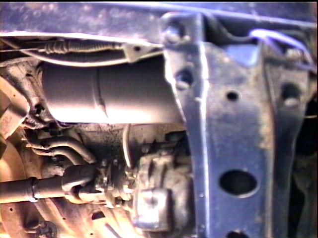 |

- Pictured (clockwise from the bottom) are the compressor, its solenoid (behind the fuse box), the air pressure gauge, the toggle switch (attached to the evaporative recovery canister) and my relocated differential breather air filter on the firewall.
- Shown are the mounting studs that attach to the wheel well. I used sections of 1/2" galvanized pipe angle-cut to fit the wheel well slope through which bolts extend up from beneath the wheel well to secure the compressor. I used my old rubber sway bar endlink bushings under the compressor to isolate vibration and allow some leveling.
- Observe the low profile of the unit. It is tucked safely out of harms way. A quick disconnect chuck is attached to the sheet metal in front of the windshield washer tank (upper left hand corner of the picture). I used a plastic cover to keep dirt out of the chuck when not in use. I carry a self-coiling 1/4" plastic hose for attaching to the front connection. I may fabricate a sort of tray to mount between the edge of the hood opening and the compressor motor. This will cover up some of the exposed power connections and also serve as a handy tool and small parts tray when working on the engine.
- Air tank mounting between the frame rail and transfer case on the passenger side. The tank is 5" dia. x 14" long, or about 1.2 gallon capacity. I ran 1/4" air line from the compressor (quick disconnect chuck) down to the tank and a return line back to the front of the hood.
I also added a quick-disconnect chuck to my Quadra-Flate tire inflator. As shipped I find this unit to requires three hands to operate, as you need to hold the central valve/gauge assembly in one, hold the air chuck to it with another and then operate the manual valve with a third hand to check the tire pressure periodically. This way, I can just chuck it in and go. In fact, I made so many modifications to my old Quadra-Flate, that I decided I should produce my own version, I call it 4air.
I tested airing up all 4 33 x 9.50 BFG M/Ts and with an empty tank and engine off, I can fill them from 12 to 32 PSI in 7 minutes. With engine on and tank full, its about 6. On the other hand, filling 4 33x15.50 Super Swamper TSL/SXs from 10 to 30 PSI takes about 18 minutes.
- For a comparison, using my 220V shop compressor (12 CFM w/ 20 gallon tank) I can air up all 4 tires in one minute 15 seconds. The difference in air flow for the two units can probably account for the difference.
- As a second point of comparison, I have heard that the ARB compressor takes 9-10 minutes to inflate a single tire (33x12.50 I think) and the motor/pump is only rated for 40 minutes maximum continuous operation.
- Another popular compressor I heard about is a portable Truck Air model. I heard from a user who reported 50 minutes/tire air up times. I don't recall the tire size in this case or if the air chuck had been modified for higher flow as some users have done.
After 3+ years of use, I've had no problems with the unit. I've modified my front bumper for use as an air tank to replace the Currie air tank to free up the space for dual battery wiring..
Cost:
  Compressor         $495
  Air Tank             75
  Mounting hardware    20
  Air hose/chucks/etc. 30
  Misc. electrical     10
  -----------------------
  Total              $630
Rating:
 and a few $$$ (but well worth it!)
Wiring:
I've had a number of people inquire how I wired the system. Below is a schematic of how the system is both wired and plumbed:
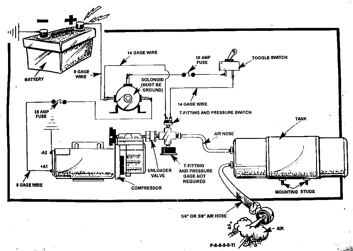
I wired my system to run directly off the battery, control logic via a 10A fuse, compressor power via a 40A circuit breaker. I have a dash-mounted switch (now) wired in series with the normally closed (NC) pressure switch and the solenoid/relay coil. Turn the switch on and if the pressure is below the pressure switch's off setting it also is closed and that sends current to the solenoid coil, closing it and sending power to the 12V compressor motor (or if using a modifed A/C compressor, this would be to the magnetic clutch on the compressor). Air flows into the tank, raising the pressure until the pressure sitch's off pressure (~100PSI) is reached, when the pressure switch opens, turning off the compressor. The compressor on/off switch is important since it stops the compressor running when you don't want it to. Since my system is wired to a constant 12 volt supply, the compressor would cycle on and off indefinitely if only the pressure switch were used. The unloader valve then releases the residual air pressure on the compressor (to make it easier to start next time) and also functions as a check valve to prevent air from leaking out through the compressor. At 80PSI, the pressure switch closes and the motor is turned back on. Later I swapped the 80/100PSI switch for a 55/70PSI version since it seems to work with my ARB air lockers better.
[Return to the top]Updates:
Air Storage:
Why the need for air storage? As discussed in another section of this page in detail, you basically have two cases with an air compressor and a given load or task. One is that your compressor can supply just the right amount of air to accomplish the task you want to do and all is fine. No storage is required. However, most of the time, you'll be in the situation where your compressor can't supply enough air for your task and you need to do something about that. Air storage is that "something". With storage, you can "capture" output from the compressor for use at a later time, like when airing up tires. Turn on the compressor and let it fill your tank while you are moving to the first tire location to hook up the air hose. Or for a light load like operating an air locker, for example, air storage eliminates the need to have the compressor turn on and off every time you operate the air locker.
Initially, I was using the one gallon air tank supplied in the Currie compressor kit. It worked, but was a bit too small for my liking, so I began looking for other air storage options. Plus I needed the use the place the tank was installed for my dual battery cable connectors.
So, I decided to plumb my front bumper for air and see if it holds air, woo hoo! I get about 1 gallon on each side. I drilled 7/16" holes on the bottom side of the 3x5" tubing, tapped for 1/4" NPT and screwed in some right angle brass hose fittings. I plan on running the air hose to the back and doing a similar conversion on the back bumper for an extra 3 gallons of air, but I ended up selling it before I got that done. My new bumper was going to be much smaller (2"x2" inside) that the amount of air it will hold is trivial.
So, I happened upon an old, retired pressurized water K-class fire extinguisher. It is made of stainless steel, holds 2.5 gallons and are rated for 200 psi. So, I picked one u[, not knowing if I could even use it, but it was worth a shot.

First, I removed the valve assembly from the tank. The pickup tube unscrews from the valve as does the outlet tube. I drilled out the rivets on the handle, punched them out and removed the valve stem. The tank supplier had suggested just attaching the tank via the a small schraeder valve used for pressurizing the extinguisher. Looking closely, this fitting is fed through a tiny hole, perhaps 1/16" dia. drilled in the valve cap. I felt this would not allow adequate flow for airing up tires/seating beads, etc. So, instead I looked to the outlet tube and valve stem, and simply plugged the 1/8 NPT threaded schraeder valve port. I left the pressure gauge on for now.
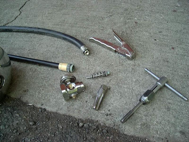
The picture above shows the disassembled valve assembly. Starting at the far left is the tank, the pickup tube, outlet tube, handle, my 1/8" NPT tap to thread it for a fitting. The outlet tube is 3/8" NPT NPT tap, my 3/8" NPT tap to thread it for a fitting. The outlet tube is 3/8" NPT NPT tap, the valve body and the valve stem in the center. I drilled out the valve stem hole and used the 1/8" NPT tap to thread it for a fitting. The outlet tube is 3/8" NPT, but is very shallow and not fully tapered as a proper pipe thread should be, so I drilled it out deeper, then chased the threads with the 3/8" tap until a standard 3/8" fitting would thread in tightly.
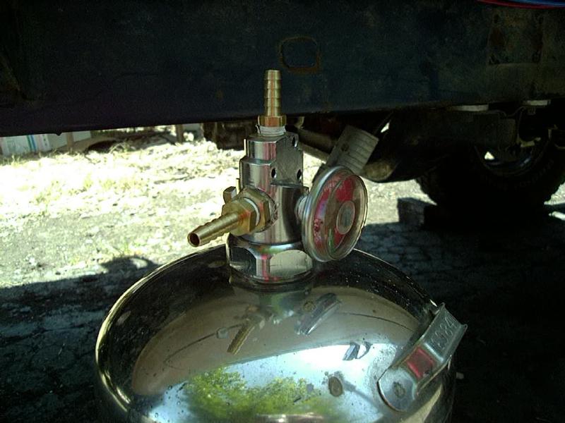
Since I use 1/4" air hose, I picked up a pair of 1/4" hose barb fittings, one 1/8" NPT and the other 3/8" NPT, installed them in the two new holes I just tapped, installed a 1/8" NPT plug in the old pressurizing port and the tank was ready to go.
I found a convenient place to mount the tank above the rear axle. With a 3" body lift, there is enough room behind my rear shocks and in front of the tire carrier to strap the tank to the floor of the cargo area in my 4Runner. I had previously left a spare fitting in my air lines to supply the tank from my compressor via one of the new ports. The second port was then used to feed a rear-mounted air chuck to allow airing up the vehicle behind me, if needed. I'll be mounting the tank with a couple of metal straps, wrapped around the tank and bolted to the floor of the bed.
The tank measures just a bit under 7" in diameter, and about 24" overall in length, the pressure vessel itself is about 21" long and has a volume of 550 cu.in. or 2.5 gallons. The tank features TIG welded heavy-gauge stainless steel construction and is rated at 200 psi. There is no provision for a drain valve, but since the tank is s/s, I plan to simply pull the tank once a year or so, tip it upside down and drain any water accumulation that way.
[Return to the top]Remote Pressure Gauge:
Great, you've got a compressor and a tank, but is there any air in it? For just filling tires, who cares? When I only used my compressor for tires, I had the switch and gauge under the hood. I'd flip it on at the end of the trail, air up my tires and turn it off. Now that I have ARB air lockers, I need to have air while I'm wheeling. So, I installed a pressure gauge in the cab, along with a switch to turn the compressor on and off. I used an EFI fuel pressure gauge (0-100 PSI) and electronic pressure sender. Since I also have EFI, I also installed a pressure sender in my fuel injector rail and ran both senders to a 2PDT toggle switch. One way it reads fuel pressure, the other way it reads air pressure. I used an Autometer 2" gauge, obtained from Summit Racing. More information on my installation is available on this page.
[Return to the top]Air Hoses:
Having and air compressor and tank on your vehicle is nice, but how to get the air to the tires? I use a custom 4-way tire inflator/deflator system. I can custom build the flexible air lines and am also building 2 and 4-tire air inflation systems, which are a perfect companion for on-board air.
[Return to the top]Other Air Sources:
A number of other sources of on-board air are available. Of the non-engine driven sources, I've compiled a list of air-up times (35x12.50 tire, measured in seconds) to use as comparison:
| Air-Up Time (secs)/ Begin/End (psi) |
Thomas TA-4101-DC |
QuickAIR | QuickAIR -II |
QuickAIR -III |
EZ-Air | ARB | Extreme Aire |
PowerTank (temp.- dependent *) |
TruckAir | Cadillac | Big Red | ND A/C Comp. |
York A/C Compr. |
| 8 / 30 | 230 | ? | 260 | ? | ? | 355 | ? | 80 - 115* | ? | ? | ? | ? | ? |
| 8 / 25 | 175 | ? | 180 | ? | ? | 265 | ? | 60- 85* | ? | ? | ~208 | ~60 | ? |
| 8 / 15 | 65 | ? | 70 | ? | ? | 95 | ? | 25- 30* | ? | ? | ? | ? | ? |
| 15 / 25 | 110 | ? | 110 | 80? | " | 170 | ? | 35- 55* | ? | ? | ? | ? | ? |
| 25 / 30 --- |
55 --- |
? --- |
75 --- |
? --- |
? --- |
90 --- |
--- |
18 - 20* --- |
? --- |
? --- |
? --- |
? --- |
? |
| Approx. Cost ($US) | $500 | $175 | $255 | $399 | $ | $200 | $380 | $300 | $40 | ~$30/used | $ | $ | $ |
| Run Time | Unlimited | min. | 40 min. | ~40 min. | min | 40 min. | Unlimited | 40 32" tires 15-30 psi |
8 hours | ? | ? | ~15 mins. Needs oiler |
Internal Oil |
| Max Amps | 26A | A | A | 46A | A | A | 60A | n/a | A | A | A | n/a | n/a |
| SCFM @ 0 PSI | 2.2 | 1.31 | 2.18 | 3.65 | ~1.0 | ? | 4.0 | ~4.2 | 0.78 | 0.17 | 1.38 | ? | |
| SCFM @ 30 PSI | 1.58 | 0.92(est) | 1.60(est) | 0.85? | ? | ~4.2 | ? | ? | ~1.0 | ~4 | |||
| SCFM @ 90 PSI | ~1.0 | 0.47(est) | 0.92(est) | (70psi max) | ? | ? | ? | ? | ? | ? | ? | 4.0 |
This data was measured without any air storage tank, except the PowerTank, which is nothing but an air (actually CO2) tank and the ARB which includes a small internal tank. The PowerTank inflation times represent figures from PowerTank (low end w/ 150psi regulator setting and from an independent test w/ unknown regulator setting). Pressures and flow rates are also subject to ambient temperature the Power Tank is used at.
The modified air conditioning compressor is also a popular air source:
- //www.onboardair.com/
- //www.jedi.com/obiwan/jeep/yorkair.html
- //www.off-road.com/4x4web/ford/bigbroncos/tech/ac_conv.html
- //www.huv.com/jon/jeep/Air/index.html
In any event, a proper air system should have a compressor, a tank, and a pressure shutoff switch. This way, they can be run unattended. With a storage tank, the compressor can continue to run while you check the tire pressure or move from one tire to another. The shutoff switch cuts off the compressor when the pressure in the system reaches a high level. My setup shuts off at 100psi and kicks on when the pressure drops below 80psi.
In evaluating air compressors, beware of the misleading specifications. For example, flow rates specified in CFH instead of CFM. Remember you need to divide CFH by 60 to get CFM. Or put it this way, do you want to inflate your tires in minutes or hours? This is often used on compressors with under 1 CFM output to make them sound "bigger". Worse yet are compressors that spec the maximum pressure they can output. While pumping 250 psi is interesting, what use is it if you only need 30 psi? Typically, what this means is that the flow rate is so low that the mfg. doesn't want to publish it, instead using the max. pressure because its a "big number".
With most any on-board air setup, there are some accessories that can make it easier to use. I find a 2- or 4-way air manifold hose works well to inflate all 4 tires to the same pressure. If you have a slow compressor, this can free you up to do other things while you wait. And if you have a fast compressor, you only need to check one pressure and have all the tires done at once. The air manifold also helps you to air down the tires. For more information, see:
Non-Compressor Options:
Several alternatives exist for putting air in tires that don't involve vehicle-mounted compressors. Two popular options are liquid CO2 (carbon dioxide) and high pressure air tanks. Liquid CO2 has an advantage of smaller tank size for a given volume of "gas", since its stored in liquid form. CO2 is measured/sold by the pound, 1 pound of liquid CO2 makes about 8 cu.ft. of CO2 gas at 1 atmosphere. You can use this figure to determine the capacity of a given size tank. Compressed air tanks, such as Scuba air tanks, are rated in terms of cu.ft., so an 80 cu.ft. Scuba tank holds 80 cu.ft. of air in a compressed state. They usually run at 2000-3000 psi. Both CO2 and high pressure air tanks will need a 2-stage regulator to reduce the internal pressure to something in the 50-150 psi range before exiting the tank.
[Return to the top]
![]()
How much air do I need?
A lot depends on what you need it for.
- If you are looking to air up tires, see the following section...
- If you need it to run air tools, you'll need to determine the air flow and pressure requirements of the air tool you are planning to use. If your air supply provides less than the tool needs, you'll have to see if the duty cycle provided by your storage and compressor will be adequate. For example, an impact wrench may be useable with 10% duty cycle (say 10 seconds on, 90 seconds off), but with a drill or grinder this may be unusable.
How much air do I need for filling tires?
If you want to skip to the Exectutive Sumary, you may do so now...
For airing up tires, you'll need to know how much air your tires hold (i.e. the volume) and how much air you want to pump into them (i.e. the pressure).
If you assume the tire takes on the shape of a torus with an elliptical cross section, you can use the following formula:
T = Tire radius (diameter/2), in inchesW = tire section Width, in inchesR = Rim radius (diameter/2), in inches
Then, you have:
r = Radius of tire body in a radial direction = (T-R)/2w = radius of tire body in the width direction = W/2
The volume of a torus is equal to the length around its center times the cross sectional area, or;
Length = (2 * pi * (R+r))Area = pi * r * w
So for a 33x12.50R15 tire, you get:
T = 33/2 = 16.5W = 12.5/2 = 6.25R = 15/2 = 7.5r = (16.5 - 7.5)/2 = 4.5w = 12.5/2 = 6.25
So the volume in cu.in. is:
Length * Area = Volume(2 * pi * (7.5 + 4.5)) * (pi * 4.5 * 6.25) = 6662 cu.in.
FYI:
- 231 cu.in./gallon and 1728cu.in./cu.ft.
so that is equivalent to:
- 30 gallons or 3.9 cu.ft.
You could refine the calculation to use the actual inner dimensions of the tire, or make estimates based upon the sidewall and tread thicknesses and use the mounted dimensions on your rim to get a more accurate number (see table below).
A crucial formula for understanding how gasses behave is the ideal gas law:
  PV = MrT
    where:
      P = Pressure
      V = Volume
      M = Mass of the gas
      r = Ideal gas constant (air is not an ideal gas, but who cares)
      T = Temperature
So how would you apply this in practice? The simplest case is to assume you have a closed system (no leaks) and you have two volumes at different pressures. Then open the valve between them and let the pressure equalize and see what pressure you end up with. Lets put some real-world numbers in here and see what happens.
Assume you had a 20gal tank at 150psi and a 4 - 30gal tires at 10psi and you then hook the tank to the tire (assumes Mass and Temperature remain constant), you'll see something like:
   Tank    +  Tire(s)  = Combined
  (20*150) + (4*30*10) = newP * (20 + 120)
(I know all those physics majors are turning in their graves with using gallons and PSI - but this is sort of quick and dirty practical physics)
solve for newP and get
(3000+1200)/140 = 30psi.
So a 20gal tank could air up four 33x12.50 tires from 10 to 30 psi. Properly, you should use absolute pressures in this calculation (you actually get the same answer), more on that later.
I've worked out some better estimates of some common tire volumes in the table below:
| OD/Width | 9.50 | 10.50 | 11.50 | 12.50 | 14.50 | 15.50 |
| 30 | 1.8 | 2.0 | 2.2 | n/a | n/a | n/a |
| 31 | 2.0 | 2.2 | 2.4 | n/a | n/a | n/a |
| 33 | 2.4 | 2.6 | 2.9 | 3.2 | 3.7 | 3.9 |
| 35 | n/a | n/a | 3.4 | 3.7 | 4.3 | 4.6 |
Assumptions:
- Tread and carcass are 1" total thickness, so inner dia. is reduced by 2" total
- Sidewall is 1/4" thick, do section width is reduced by 1/2" total
- 15" diameter rim measurement
So, cool, throw a 20gal. air tank in your truck and head out wheeling. You'll be able to air up at the end of the day and drive home. I have a 20gal. air tank and the thing is *huge*. Not sure where I'd put it or how I would tie it down. Now, if you don't happen to have a large enough air tank, you are going to have to rely on the output of the compressor for some or all of the air needed to fill the tire(s).
Compressors are typically rated at some air flow rate (SCFM) at a given pressure (@PSI). It is important to consider how this is measured and what it really means. First the S refers to standard temperature and pressure, usually 20°C/68°F and 1 atmosphere (1 bar, 14.7 psia) pressure. The CFM part is Cubic Feet per Minute *at* the standard temperature and pressure. Finally the @PSI part refers to the pressure of the air as it exits the compressor, usually this is expressed in gauge pressure (psig). Quite often SCFM ratings at various pressures will be given, with lower SCFM ratings for higher pressures.
You might then ask at what pressure the CFM is measured. Whenever people talk about air compressors, they always refer the volume of the compressed air measured at the standard atmospheric conditions. For example, if a compressor delivers 1 SCFM@90 PSI, it means that the compressed air occupies a much smaller space inside the compressor (at 90 PSI), but if you could un-compress the air back to standard conditions then it would fit inside a box measuring 1'x1'x1'. Or to put it another way, think of the SCFM as how much air is being "sucked into" the compressor in a given time.
OK, so now we understand SCFM and PSI and all that, but how do you relate that to time required to fill a tire to a given pressure? The correct answer would require a lengthy dissertation on integration, thermodynamics, etc. But a simpler way to approach the problem is to consider the difference between gauge and absolute pressures. Since we live under an ocean of air, the ambient sea level air pressure is 14.7 psia (or absolute). If you take a tire and remove the valve stem, allowing all (actually most) of the air to escape, then put a tire gauge on it, it will read 0 psi(g). Why doesn't it read 14.7? Because it is reading a relative pressure, or the difference between whatever its hooked to and the atmosphere. To measure absolute pressure, you need a fancy gauge that has a vacuum for a reference.
So, you really never have a tire with no air in it, the first 14.7 psia comes for free! Anything above that takes some work. So, when you say you air up to 30 psi(g) you really are going from 14.7 to 44.7 psi(a). Anyway, going back to the ideal gas law, it says that:
PV = MrT- or -P = MrT/V
If we assume constant temperature and volume (the tire does stretch some, but not a lot), you'll notice that the pressure is proportional to the mass of air in the tire (air weighs about 0.1 lb. per cu.ft. and yes, I know lbs. is a measure of force, not mass, but what the heck, when we start wheeling on the moon, I'll rewrite this). So, lets start with a 3 cu.ft. tire at 14.7psia (0psig) and pump in another 3 cu.ft. of air, the absolute pressure will double, from 14.7 to 29.4, the gauge pressure will go from 0 to 14.7psig. So, the key is to think in terms of "atmospheres" (or bars) of pressure change that you want. For ease of calculating, just think that every 15psi change will require adding one tire volume of air to the tire. Don't worry about the start and end pressures, only the difference is important.
Actually, that's not really true in the real world, as the pressure builds inside the tire, the compressor has to work harder.
Typically SCFM drops off as pressure rises. So, the time to air up from 15-30psi will be shorter than from 30-45. So, try to determine your compressor's output at a typical inflation pressure.
So, the key is to determine how many standard cubic feet of air you need to provide a given pressure change, then divide that by the SCFM output of your compressor to get the time required. When I tested my Currie unit, it aired up 4-33x9.50 tires from 12 to 32psi in 7 minutes, so how does this compare to theory?
  P = (32-12)/14.7 = 1.36 atm
  V = 4 * 2.4 = 9.6 cu.ft.
  P*V = 1.36 * 9.6 = 13.1 SCF
  Time = P*V/SCFM = 13.1/2.2 = 5.93 minutes
So, that comes out pretty close to the measured time, in fact my air up time with the engine on (alternator boosting system to ~14 volts, vs. 12 volts from the battery, which makes the compressor go faster, which is probably where it is rated at anyway) was right at 6 minutes.
Conversely, you can find out your average flow rate given the amount of time required to change the pressure of a known volume of air. Using the Powertank air-up time for example, we know it takes 80 seconds to inflate a 35x12.50 tire from 8 to 30 PSI.
  Converting the change in pressure to atmospheres, give (30-8)/14.7 = 1.5atm.
  Air volume from Table 2 is 3.7 cu.ft.
  Time is 80/60 or 1.33 min.
  SCFM = P*V/Time or SCFM = (1.5) * (3.7) / 1.33 = 4.2 SCFM
A third option is if you have a large and/or high pressure storage tank that can hold 100 cu.ft. or more of air, you can simplify the calculations to some degree by dividing the volume of the tank by the volume of the tires. For example, using a 2.0 cu.ft 30x10.50 tire and say a 2000 psi/100 cu.ft. tank, you should be able to fill something like 50 (100/2) tires from 15 to 30 psi (i.e. a 1 atmosphere change in pressure).
Granted, all the above results are only approximations, there is heating and cooling of the air and other factors, but they come up with results that are "close enough".
Anyway, a couple of key points to take away from the above:
-
Tires hold a lot of air
- Big tires hold even more air than smaller tires
-
Tanks don't hold a lot of air
- Unless they are really big or at a very high pressure or use liquid phase storage like CO2
-
Compressors pump air
- Small compressors pump a little air
- Bigger compressors pump more air than smaller compressors
- And the key point is that you can never have enough pumping or storage capacity
One important point to remember with a hard-mounted on-board system is that you need to ensure you can supply air to your tires. You need a long enough hose to reach all 4 corners. I found a better solution with an air hose setup that reaches all 4 tires at the same time, and insures they receive equal amounts of air. More information on that is available here.
[Return to the top]How much air do I need for air tools?
This is an easier question to answer than filling tires with air.
-
First off, look on the air tool for its required air consumption
- This is usually given in CFM at a specific pressure, typically 90 PSI; call this "A".
-
Now look at your compressor's output; call it "B".
- If it B > A, you are set, hook up the hose and you can run forever.
- If A > B, then you need some storage capacity and have to deal with duty cycle.
A rough estimate of duty cycle can be determined by dividing B by A (B/A*100% = duty cycle). For example, if your tool requires 4 CFM and your compressor puts out 1 CFM, you could expect to run the tool (4/1*100%) = 25% of the time, while the compressor catches up the rest of the time. Duty cycle is a percentage, in the example this could be 1 second on, 3 seconds off. How long the "ON" time is depends on how big the air storage is. Now the coverse of the on-board air solution (where you are typically compresor limited), for a shop compressor, generally the compresor will put out more air than the tools require. So in that case, while B > A, the ratio of A/B will give you an approximation of the compressor duty cycle. So for say a 4CFM air tool and a 12CFM compressor, you would expect the compressor to run about 1/3 of the time (4/12 = 1/3) and the remaining 2/3 of the time the air for the tool would come from the air tank.
You'll need to determine what a useable run-time is for the tool. For example, using an air impact wrench for removing or installing wheel lug nuts, being able to remove or install all the nuts on a wheel would be ideal and doing one nut would probably be a bare minimum, with the natural break in the process while you move from nut to nut or wheel to wheel allows time for the compressor to catch up. Given the length of run-time and the tool's air consumption, figure out the amount of air storage you'll need, using the above volume and pressure formulae.
With my Thomas compressor and a 1/2" drive, 350 ft.lb. impact wrench and a 2 gal. (1/4 cu.ft.) air tank, I found I could remove 1 wheel lug nut in about 5-7 seconds of run time. The impact wrench is rated at 4 CFM the compressor about 1 CFM@90 and it took perhaps 20 seconds or so for the compressor to shut off at the 100 PSI limit. In this application, I did have to wait for the tank pressure to rise, to ensure maximum torque was available for breaking the next lug nut loose. I probably need (and plan on adding) more air storage in my system and some extra pumping capacity probably wouldn't hurt either. On the other hand, my shop compressor can usually remove all 6 lug nuts from a wheel in one cycle, although available torque drops as the tank pressure falls.
Another option is if you have a large and/or high pressure storage tank that can hold say 100 cu.ft. or more of air, you can simplify the calculations to some degree by dividing the volume of the tank by the CFM rating of the tool. For example, using 2000 psi/100 cu.ft. tank, you should be able to run a 5 CFM air tool for approx. 20 minutes (100/5).
One other factor to consider is that compressors usually have a pressure switch that controls operation of the motor. They are set up with a "dead band" to avoid cycling the compressor and motor on and off too frequently. For example, my OBA system is set up with a switch that closes below 80 psi and opens above 100 psi. Your compressor may have a different on and off pressure setting, but about a 20% dead band is common. So, how does this figure into the duty cycle calculation of the compressor. One way to look at it is that it makes the tank seem to be 5 times smaller than it actually is. So you may have say a 20 gallon tank, but once you remove ~20% of the air (about 4 gallons), the pressure will fall 20% and that will trip the motor and compressor to start running to replace that 20%.
This may or may not matter depending on the nature of the air tool you are using and the relative CFM ratings of the tool and the compressor. If your compressor puts out more air (in the 80%-100% pressure range) than the tool uses, the compressor will ultimately re-fill the tank while you continue to use the tool. That is, as long as the tool you are using works effectivly below 100% of the maximum pressure. For example, a grinder or drill will probably work fine, since they work more off of air flow and not so much with pressure. Something like an impact wrench may be affected, especially if you are trying to bust loose some very tight fasteners are near the torque limit of the gun, as I find the impact torque falls off quite rapidly with falling pressure. So you may need to wait for the compressor to "catch up" to 100% pressure before breaking the next nut or bolt free.
[Return to the top] Back to my Cheap Tricks page.
![]()


Visitor # since 28.AUG.2001
[Last updated: 21.November.2022]
![]()