Toyota Front Axle Rebuild
![]()
Introduction:
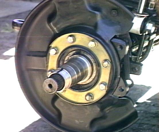
Ever wonder what your front axle would look like *without* all that grease an oil caked on it? Well, I did, but didn't want to find out *that* bad. However, after getting my Birfield joints replaced with Marfields, I started experiencing an oil leak on the passenger side of the axle. Attributing it to a worn felt and rubber seal on the steering knuckle, I picked up a new seal kit and replaced the outer seals on both sides. It seemed to work for a few months then all of a sudden my little leak was a BIG leak, I had oil all over the rim, tire and underneath the truck.
Here's how I did this project:
Tear Down:
Start by getting a container to hold the nuts/bolts in.
- Jack up the wheel to be worked on
- Take tire/rim off the truck
- Remove the 2 caliper bolts (17mm) and either disconnect the brake line from the caliper or support the caliper so that the brake line is not too distorted.
- Unscrew the 6 bolts holding the locking hob dial on (this is assuming you have manual locking hubs). Pull the hub dial off.
-
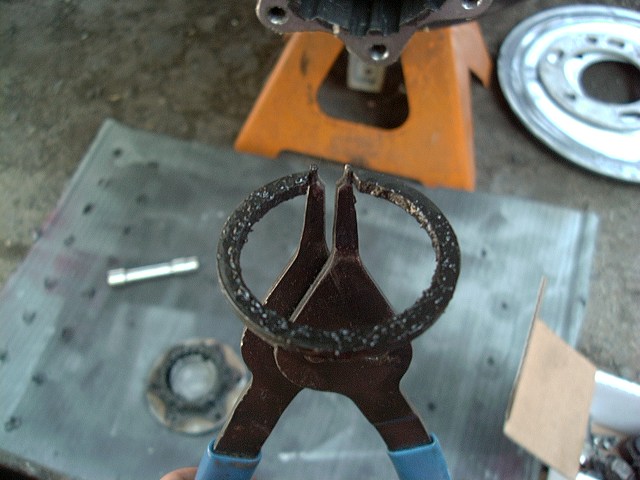
Remove the snap ring in the end of the axle:
- I found that if I ground a small groove in the outside edge of the tips of the snap ring pliers, its was much easier to remove and install the outer snap ring if your axle has the sharp ended variety. Sometimes the clip is the type with tabs and holes on the end, so a normal external snap ring plier is fine.:

Next, cone washer encounters of the first kind:
- Now, unscrew the six nuts holding the hub body on out till they're flush with the ends of the studs.
- If you haven't ever had them off, it might be good to start a few days early by soaking the studs with WD-40 or your favorite rust-bustin' lube (PB Blaster is pretty good stuff) in case the cone washers are rusted in place.
- Take your brass drift or steel bar and place it on the ends of the studs/nuts firmly with a hammer.
- This is to remove the cone washers that are holding the hub body on.
- Give it 2-3 firm blow then rotate the hub and hit the next.
- Don't just wail on them, but hit them firmly.
- They can be a bear to remove on some trucks, just don't hit the hub body so hard that you deform it.
I tried the above technique on my cone washers and found it worked on a few, but not all of them. After some experimenting, I found that a narrow bladed screwdriver and small hammer worked 100% of the time. Just line the screwdriver blade up with the cone washer slot and give the screwdriver handle a few raps with the hammer. Anyway, the idea is that you push something into the slot in the washer, expanding it a bit, causing the cone washer to push against the tapered hole and it'll just climb right up the stud. Works like a charm and is much more elegant that beating on the hub with a big club! See below for an animation of the process by Joshua Carlson:
Then again, on my spare axle, which appeared to be totally stock and had never been taken apart, the screwdriver technique didn't work but a quick tap with a hammer on the hub popped off one after another cone washer with ease (several of which flew off with such force, that if I didn't have the nut loosely on the end, I would have lost them as they flew off into the grass).
A third technique is to use a small chisel to turn the washers and break them loose. Fit the end of the chisel into the slot of the washer and angle it to one side. Tap with a hammer to loosen the washer.
A forth technique for removal, submitted Peter Bonefant of Ontatio Canada, is to simply remove the stud and the cone washers as a unit, by double-nutting the threaded end of the stud, then back out the stud from the hub body. I imagine this would work well for cone washers that are slightly more deformed. Sounds like a good last resort, a bit more time consuming, but should work in most every case.
Here's a YouTube video of my technique
The important point is that there are many techniques to try, if one doesn't work, try another...
- Remove all 6 cone washers
- Remove the lock ring from the end of the axle shaft
- Pull the hub body off
- Beat the tabs of the lock washer back that are holding the outer spindle nut in place.
- Remove the outer spindle nut
- Remove the lock washer
- Remove the inner spindle nut
- Grab the brake rotor firmly and just pull the whole assembly off the spindle and trying not to dump the outer bearing out on the ground when it comes off the spindle.
- Remove the outer bearing from the hub and the washer that presses against the outer bearing.
- A seal puller helps to remove the seal that holds the inner bearing in
- Another option is to turn the hub upside down and tap the bearing/seal out the back side. Be careful doing this if you're planning on re-using that bearing as you can damage it easily.
Now that you've the hub completely disassembled. It's time to get the races out of the hub body for the bearings you want to replace. I use a brass bar. It's sort of tricky getting those races out since there isn't a very large surface of the race to hit on. Just hit a little on this side, a little on that, side, going back and forth and it'll come out, but definitely use a brass *something*, not steel!
-
Remove the spindle and remove it and the seals and gaskets behind it.
- Take careful note of the order of the parts for subsequent reassembly.
-
Now the Birfield joint can be removed, if needed:
- Line up the flats of the Birfield joint with the knuckle bearings and pull it out along with the inner axle.
- Remove the cotter pins and loosen the nuts on the tie rod ends, just until the nut is at the top of the stud.
- Now, use your favorite tie rod pulling technique, BFH, pickle fork, or mine is a propane torch, heat the stud until the opposite side just starts to smoke, put down the torch, grab the hammer and a light tap should pop the tie rod loose.
- Remove whatever other steering linkage, like drag links, etc. from the steering arms.
- Next, remove the nuts holding the upper steering arm and lower bearing caps and...
Cone washer encounters of the second kind:
- Bigger washers, similar technique as the ones on the hubs, 4 on top, 4 below.
-
Use a hammer to loosen the steering arm from the knuckle bearing (hit
up where the tie rod was connected).
- Once loose, a flat chisel can help lift it evenly.
- Remove the keep the upper and lower shim stacks separate so you know what sort of shims to put back on the upper and lower bearings.
-
Use a long brass punch to pop the lower bearing cap off from above.
- If the trunion or knuckle bearings are being replaced, use a long punch to pop them out the the seats in the steering knuckle.
- There are two small semi-circular notches in the seat where the tip of a punch can reach the inner lip of the race.
- If you'll be replacing the bearing, use a steel punch on the race and tap it out with a hammer, alternating side to side.
- Remove the inner oil seal, you'll be replacing it anyway (you did buy a pair, right?)
So, what do you do with that big, greasy Birfield/axle assembly. You really need to clean it well and the best way to do that is to separate the axle and Birfield. A large metal tube, long enough for the inner axle to slide into and small enough to contact the Birfield housing works great. Put a rag at the bottom of the tube (to prevent damaging the splines when it pops loose), drop the inner axle into the tube and slam the whole Birfield assembly onto the tube until the inner wire clip breaks and lets the inner axle drop out.
Then, clean that sucker out really well. I used a parts washer and left the solvent pump circulate solvent inside the housing for an hour of so, to dissolve every trace of crud in there. Then dry it off and use a blast of brake cleaner to get the solvent residue off. Refill the joint with CV Joint grease, its specially formulated for CV joints, of which the Birfield is a variety. Some folks use a moly fortified wheel bearing grease.
A couple of tips for handling the bearings and races.
- Be sure to keep track of which bearing came out of which location. It is important to put the bearing back into the same race it came out of, or if replacing bearings, also replace the race with the one that came with the bearing. Supposedly, according to one story, bearings and races are precision matched at the factory. While this may or may not be true, but perhaps it is based in part on the following tip which is true. If you replace a bearing, you must also replace the race, because the race surface is hardened, but the hardening only goes so deep. If it wears through, the race will begin to pit and spall, which will cause bearing failure. The same is true for the roller bearings themselves. So it just stands to reason if one part failed for whatever reason, the part it was in contact with has seen similar conditions and is probably near failure itself.
- Make sure the locating pins of the steering arm and bottom cap fits easily into the center of the knuckle bearings. You want a snug fit but if you have to hammer the steering arm or bottom cap into place, you'll be hating life the next time you try to take the knuckle apart! This is especially true of the after market crossover steering arms, they tend to have pins that are slightly bigger than stock in my experience. If you can't slide the bearing on and off the pin without force, use a piece of emery cloth to clean up the pin and then test fit the bearing. Repeat as needed to make for a good fit.
- For greasing the knuckle bearings, use whatever grease you want. If you have left over CV joint grease from the Birfields, use that. Otherwise any sort of wheel bearing grease is fine, I typically use a moly fortified high temperature wheel bearing grease for this. Again, two schools of thought are to use just enough grease for the knuckle bearings. Other folks like to nearly fill the entire knuckle with grease. If the latter is your choice, probably best to use the same grease inside the Birfield since they will likely mix any way.
To tack or not to tack?
That is the question.
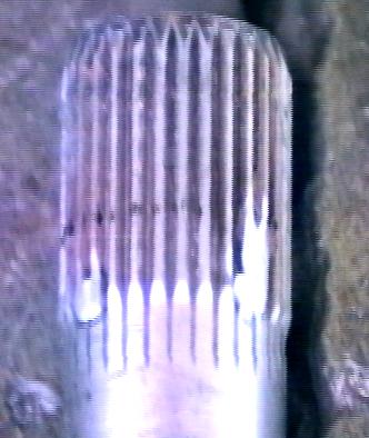
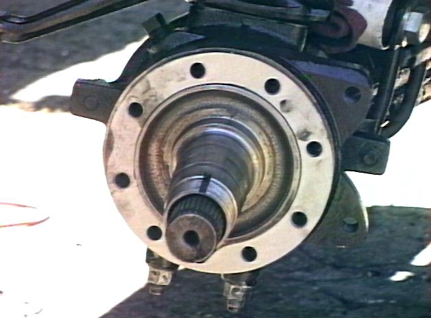
I say tack, but you need to do it in the right place. I had my inner axles MarTacked when the Marfield joints were installed and guess what, the MarTack led to the oil leak that led to me rebuilding my axle. On the left, you can see the "official" MarTack, place 1-3/8" from the end of the splines. On the right, you'll see my TrueTack spaced only 1-1/8" from the end of the splines. My front TrueTrac differential carrier is apparently a bit narrower than the stock unit, upon which the crucial MarTack distance was determined.
- Note:
- Where did the term MarTack come from, you might ask? Marlin (of Marlin Crawler fame) was one of the first people to come up with the idea of using small tack welds on the inner end of the axle to replace the function of the little C-clip that normally holds the outer end of the axle inside the Birfield joint. This makes train repairs of broken Birfields easier, since you can carry only the joint and you avoid the need to hammer or pound the broken Birf off the inner axle.
I recently swapped my 4-cyl. 3rd member w/ TrueTrac for a high-pinion FJ-80 diff with an ARB RD23 air locker. I found that once again, the "right" location for the tack welds was between 1-1/8 and 1-1/4". This time I also made sure and placed all three welds, I had trouble with a single weld wearing through.

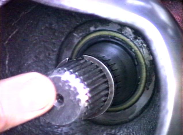
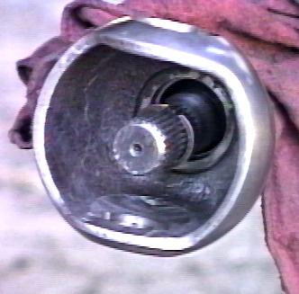
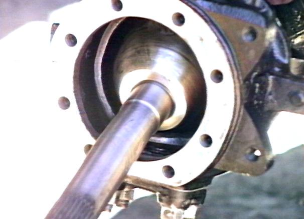
Anyway, what the MarTack does, is to prevent the inner axle from slipping too far into the axle housing. This serves two purposes, one is to keep the spline engagement about equal between the differential carrier splines and Birfield, second is to keep the raised, machined oil seal surface under the inner oil seal. In the picture on the left, you can see the inner axle pulled out to reveal the shiny raised surface. The picture on the right shows how far the axle should push into the housing. You'll notice the flat surface has just disappeared into the seal, but no more. Before moving the tack weld, it went a full 1/4" farther in, causing the oil seal to leak around the smaller axle shaft itself.
The c-clip on the axle prevents it from moving too far into the Birfield, so between the tack and clip, the inner axle can move about a little but not too much. You can feel when the inner axle seal drops off the sealing surface the axle can move around a bit more. If this can happen by hand, it WILL happen when you put the axle back together and it WILL leak gear oil and you WILL get to rebuild the axle again! I used a depth gauge on a cheap caliper to measure how far the axle moved in after the axle dropped off the seal and used this to place the final tack weld. Once I got it set right, I added two more tack welds around the same depth, 120° apart, ground them flush and that was it.
Some differentials don't seem to require any tack welds or clips inside the Birfield as the "guts" of the diff prevent the axle moving in too far. Conversely, other types need something to prevent this from happening. On the other hand, you don't want to put the tack welds any closer to the end as you need. The axle should have room to float around a little, otherwise it will put pressure on the inner race of the Birfield, probably not a wise thing to do, either.
Anyway, you have three options for installing inner axles:
- Use the clip (and carry either complete axles for spares or a separator tool)
- Use tack welds at the right spot
- Use nothing
Which option you use depends on your axle and your differential carrier. Use whatever works for your situation.
Here is another writeup showing a very similar technique for determining the proper MarTack location.
Birfield/Inner Axle Separation:
Of course the above implies that you have separated the Birfield joint from the inner axles. I find a length of metal pipe just large enough to slip the inner axle into and long enough to enclose the inner axle works well. Stand the pipe up on end on a rigid surface, concrete or rock works best; dirt, wood, and asphalt can be too "bouncy". Put a rag down the tube to protect the end of the inner axle and drop the whole assembly down onto the end of the tube. The impact and inertia of the inner axle will pop it loose from the birfield, usually leaving the inner clip intact. If a low drop won't work, gradually raise the birfield up higher and drop it. On the short side axle, you may need to "throw" the axle into the tube to get it loose.
An alternate method, and a good trail fix, is to ram the inner axle and birfield into the round tube crossmember that runs across the top of the frame in the rear wheel wells. Its the right size to fit the inner axle in. Do the long side first and then you can use the long inner axle to push the short side axle out if it stops in the middle.
[Return to the top of this page]Rebuild:
Then you may feel inclined to clean and paint the hub/axle/etc. while you've got it this far disassembled. I used a combination of rotary and orbital sanders to remove the pitting from the steering knuckle ball. It took some time to get it smooth but I think it will help the seals both seal better and last longer. Also be sure to remove the old inner axle seal and replace it while the knuckle is open.
Here's a really cheap trick, that can be done anytime, but is easy while you have the axle torn down. Pull those square plugs on the knuckle housing (you know the ones you try to pump grease into, not gear oil, right) and drill and tap a hole for a grease fitting. I installed a 45°angled grease Zerk in each plug and now its easy to shoot a little extra grease into the knuckle if needed. With the crossover steering arms in the way, access to those plugs is limited, but its easy to pop a grease gun on the Zerk.
Below, you'll find a diagram of the parts assembly for the steering knuckle, bearings and spindle.
-
If the knuckle bearings were removed, reinstall them now, tapping the
new race into the cleaned seat on the knuckle.
- I used a rubber mallet to tap thep into place, chilling the races in a freezer for a few hours can held with the installation.
- Make sure to bottom the race out in the seat, you can check this by looking at the little notches where you drove the old race out, there should be no gap visible.
-
Check the fit of the knuckle bearings
over the studs on the steering arm and lower knuckle cap.
- If the bearings do not slide on easily, consider sanding down the stud lightly to remove any burrs.
- You do not what to force the bearing onto the studs, or you will regret it next time you need to take things apart!!!
-
When reinstalling the steering arms and lower knuckle bearing
retainers, be sure to install the appropriate shims.
- I think mine were bone stock when I took them apart and there were no shims.
- The rebuild kit came with a huge stack of shims. I at first put the knuckle back together w/o shims and found it was overly tight.
- After asking around, the consensus seems to say 0.40mm (or 0.040" I don't know what units are used ) of shims is the right amount.
-
The factory manual describes a bearing drag measurement technique if
you prefer:
-
Use a fish scale to pull on the steering arm until the break-free pull
is 7-13 lbs.
- Some folks prefer a bit higher preload with larger tires and use ~15 ft.lbs.
- Do this without the knuckle wiper seals installed, just the knuckle bearings.
- Add thicker shims to decrease the bearing drag and thinner shims to increase bearing drag.
-
And you'll want to keep any shimming equally split between the upper
and lower bearing to keep things centered and to keep the pre-load on
the upper and lower bearings somewhat equal..
- If you add or remove shim on top, do the same on the bottom.
- The only time you would not do this is if you are trying to re-center the axle inside the knuckle, in which case you'll need the SST to measure the centering and follow the instructions that come with the tool for shimming.
-
Use a fish scale to pull on the steering arm until the break-free pull
is 7-13 lbs.
- Be sure to pack the knuckle bearings before installing them.
One tip is that the above diagram is missing one crucial component in the assembly of the spindle. That is the brake backing plate or backing plate eliminator (a.k.a. spacer). Some folks opt to purchase a pre-made spacer ring to eliminate the bulky factory backing plate, others just trim away all but the inner ring of their backing plate to make this part. But in any even, you need to run something there for proper assembly of the spindle. So in the above diagram, you see the knuckle, a gasket, the spindle, another gasket and finally a seal. The critically important missing component is the backing plate or eliminator piece. It MUST be placed outside of the spindle as shown below. The thick ring of the backing plate or eliminator fills in the recess in the rim of the spindle and provides a flat surface for the outer hub seal to bolt to. So the order of assembly is the knuckle -> gasket -> spindle - > backing plate -> gasket -> seal. Also, the seals may fit best on one side or the other, so make sure to test the bolt hole alignment before proceeding. In the far right image below, you can see the completed assembly. If you leave out the spacer or backing plate the seal will be deformed into the recess in the spingle flange. And if the spacer is put between the spindle and knuckle, it will push the hub too far outwards for the brake caliper to fit properly. One nice upgrade for the spindle attachment is to install studs into the threaded knuckle holes. Then it is a much simpler process to slide the various gaskets and pieces over the studs for assembly. This is 10x easier than trying to hold 2 paper gaskets, a heavy steel spindle, a bulky brake backing plate (or eliminator ring) and a seal in place with greasy hands while trying to get 8 small bolts inserted into deep holes and threads started in order to hold things in place. So knuckle studs = thumbs UP!
Once the knuckle bearings are installed, insert the inner axle and birfield into the axle housing. Be careful to support the inner axle (especially on the long side) as you slip it in past the inner seal. At the very end, you need to do two tricky movements at once, that is getting the end of the inner axle into the splines on the differential carrier and at the same time getting the flats of the birfield joint past the knuckle bearings. It helps if someone can turn the pinion flange back and forth while you work the birfield into position. I like to start with the short side first, since its a lot easier. Once installed, put on the spindle, brake backing plate and seal and the retaining bolts (or stud kit).
- Knuckle bearing cap nuts are torques to 71 ft.lbs.
- Spindle bolts (or nuts on studs) are torqued to 38 ft.lbs.
There seem to be two schools of thought pn how much grease to use, one is to pack the knuckle full of grease and the other is to just put in "enough". I like the latter, the birfield itself gets packed full (that's where all the action is anyway) and then put some around the knuckle to keep the knuckle bearings lubricated. I like to leave some air space to allow for expansion when the axle heats up and prevent the excess grease from being forced out past the felts. In areas where lots of deep water and mud exist, the full pack might help to keep water out of the knuckle. But since the areas I wheel are fairly dry, I prefer to use a minimum amount of grease, since whatever grease you pack in there while rebuilding will have to be cleaned out the next time you have to open up the knuckle.
Then proceed to assembling the wheel bearings:
- Drive in the new race(s) in the same manner as removing the old race.
- Pack new inner bearing, put in inner bearing
- Drive in new seal
- Pack outer bearing
- Either put outer bearing into it's race and slip whole unit onto spindle or slip unit on spindle then put outer bearing in. Be careful not to dump new/clean outer bearing on ground when putting it on spindle.
- Put washer with tab on it for the slot in spindle on.
- Put inner spindle nut on.
Now there are two schools of thought on properly tightening the wheel bearings. First is the method documented in the Toyota Factory Service Manual:
- Tighten the nuts finger tight, then using a spring scale, measure and record the seal drag while turning the hub with the scale attached to a wheel stud
- Then tighten the nut and re-measure the bearing drag until it reads about 3-8? lbs more than the seal drag alone.
The second method seems to produce similar results and is a bit more straight forward:
-
Torque spindle nut to 43 ft. lbs.
- Spin hub right 4-5 rotations
- Spin hub left 4-5 rotations
-
Loosen inner spindle nut
- Spin hub right 4-5 rotations
- Spin hub left 4-5 rotations
-
Torque spindle nut to 43 ft. lbs.
- Spin hub right 4-5 rotations
- Spin hub left 4-5 rotations
-
Loosen inner spindle nut
- Spin hub right 4-5 rotations
- Spin hub left 4-5 rotations
- Torque spindle nut to ~21 ft. lbs.
The idea behind the second method is to ensure the bearing is fully seated in the grease and then the final torquing sets the pre-load fairly accurately. I used the second technique on my first rebuild (I didn't have a spring scale then) and I found the bearings a bit tight. In fact they seemed to be getting a bit hot on a highway trip to go wheeling. However, after two days crawling rocks, they seemed to settle right in. When I got back, I picked up a scale and measured the bearing drag and both sides were about 8 lbs. total (don't know what the oil seal drag was and I wasn't about to find out :-), so I guess it worked OK.
In any event, you are on the home stretch and the procedure follows:
- Put on locking tab washer
- Screw outer spindle nut on till it's fairly tight
- Bend one tab on the locking tab washer forward onto the inner nut and one outward onto a flat side of the outer nut
- Put locking hub body on
-
Put cone washers and nuts on studs (coat the cone washers with
anti-seize so that the next time you do this, the cone washers will
just pop right out with one blow)
- 12mm head, torque to 23 ft. lbs.
- I find that if I use a tapered punch to open up the cone washers a bit, then run a round file along the inside of the split, they go on and come off much easier
-
Install the c-clip/lock ring on the stub axle
- Handy tip if you find the stub axle slides back into the hub too far to allow the snap ring to fit into the groove is to grab an M8-1.25 bolt, something like 25-50mm long and thread into the hole in the end of the birfield stub axle. Then you can pull out the stub axle with the end of the bolt while pushing the c-clip into the ring.
- Also helps to use a flat bladed screwdriver to push back on the clip around it's circumference if it is not seating all the way. You want to see an even depth all the way around the end of the axle with the c-clip.
-
Install hub dial and it's 6 bolts
- 10mm head, torque to 10 ft. lbs.
- Wash the brake rotor down with an ozone-depleting blast of brake cleaner
-
Bolt caliper back up
- 17mm head, torque to 68 ft. lbs.
-
Reattached brake line if it was disconnected
- I like the brake hose clip on my crossover steering arms, no need to remove the brake line
- Put tire/rim back on
Cost:
   Description               P/N             Qty     Cost('98) Comment
   -------------------------------------------------------------------------------
   Knuckle Rebuild Kit       04434-60015       1      $92      Gaskets and shims
   Outer axle oil seal       90311-62001       2       20/pr.  Optional
   Inner axle oil seal       90311-33085       2       12/pr.  Recommended
   Steering knuckle Bearing  90366-17001-77  0-4       30/ea   Dealer or rebuild kit
   Wheel bearing, inner      90368-     -77  0-2         /ea   Aftermarket cheaper
   Wheel bearing, outer      90368-45087-77  0-2       44/ea   Aftermarket cheaper
   -------------------------------------------------------------------------------
Another nice option, is All pro Offroad's Knuckle Rebuild Kit, it seems to include all the gaskets, the two different oil seals, a full set of knuckle bearings, and new "star" washers for the spindle nuts, in one package. You may need to purchase wheel bearings and races separately, if needed. Another neat kit All Pro Offroad offers is a spindle stud kit, which replaces the bolts that hold the spindle to the knuckle (really fun trying to line up the spindle, gaskets, oil seals, brake backing plate and get the bolt into the hole in the knuckle) with easier to use studs and nuts. I'm planning to install this kit next time the axle is apart.
- Other sources of rebuild kits include:
-
//www.marlincrawler.com/
- //www.jtoutfitters.com/
- //www.sor.com/
- //www.jtoutfitters.com/
Tools:
Tools/supplies you'll also need:
- The elusive 54mm (2-1/8") socket for the axle nuts and a torque wrench to turn it with
-
A pair of snap ring pliers to remove the axle C-clips:
- I modified mine by filing a groove on the outside of the tips to keep the ends of the snap ring from slipping off
- : Carry both of these tools with you on the trail, you won't regret it!
-
A brass punch to drive the races out and a dead blow or rubber mallet
to pound them back in
- A seal puller is also handy, but an assortment of screwdrivers will work
- Rags, lots of rags, to soak up the...
-
Solvent, lots of solvent, to dissolve the remnants of...
- A parts washer is nearly indispensable for this task
-
Grease, lots of grease, a couple of pounds to repack everything with:
- I used a bucket of disc brake wheel bearing grease, use it in the knuckles and wheel bearings
- And a tube or two of CV joint grease to fill the Birfields with
- A bearing packer would be a good idea, I got one after doing this job the first time
Project Rating:
 - Expect about 2-2.5 hours per side, longer if cleaning/painting.
[Return to the top of this page]
Links to more information
If you'd like a second opinion on this project, I researched this project and found a few good write-ups on the web:
-
4x4Wire has an excellent
write up on Toyota Front-end Maintenance:
- //www.outdoorwire.com/4x4/toyota/maintenance/front_end/
- This page includes information on rebuilding the IFS front end as well
- Tips and Techniques on Repacking CV (Birfield) Joints and Wheel Bearings
- Some front axle threads on Barney's Toy4x4 e-mail archive
- Morgan Fletcher did a very detailed front axle rebuild write-up
-
Here are some tips on rebuilding the stock Aisin manual locking hubs
- //www.off-road.com/toyota/tech/aisin/index.htm
- //www.yotatech.com/f115/toyota-aisin-manual-hub-101-sfa-vs-ifs-reassembly-186269/
- Applies to both solid axle and IFS front hubs
- And a humorous story to read after you finish the job!
![]()


[Last updated: 04.May.2024 ]
Visitor # since 28.AUG.2001