Combined Parking/Turn Signal Lights
Contents:
Back to my Cheap Tricks main page.Introduction:
Many Toyota trucks have separate turn signal and parking light assemblies. The parking light is mounted in the front edge of the fender and the turn signal is recessed in the front bumper. While this setup works fine with the factory bumper, it causes problems with many after-market bumpers.
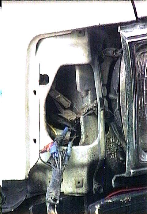
Here's an example of how the stock turn signals mount on a typical aftermarket dual tube front bumper. The turn signal mounts on the back of the bumper, between the two tubes. A long screw passes through a triangular bracket and the lens to hold it in place. This setup can cause trouble in the winter, as snow can pack in front of the turn signals, getting trapped between the bumper tubes and the mounting bracket. Unless the snow is periodically cleared, it will mask the front turn signals. Also the wiring is exposed behind the bumper, directly in front of the wheel well.
My other vehicle has a fender-mounted turn signal/parking light assembly that utilizes one socket holding a #1157 dual-filament bulb. This seemed like a better solution, so I set about designing a retrofit for the Toyota parking light assembly. I went to the local auto parts store and found a universal dual-contact lamp socket (Calterm #08547) for an #1157 dual-filament bulb. Note that this is the same bulb that is used in the rear parking/brake light socket. The socket is about 3/4" in diameter and includes a separate metal mounting plate. The #1157 bulb is about 1" in diameter, so this determined the size of the hole in the back of the reflector.
[Return to the top of this page]Modifications:
Take out the stock lamp socket and enlarge the hole to the diameter of the bulb with a small grinder. Then, use epoxy putty to build up the back of the reflector to provide a flat surface for the mounting plate. This accomplishes two important functionsL
- Moves the mounting surface of the socket away from the back of the housing to allow the larger 1157 bulb to fit inside
- Adds thickness to the back of the light to hold the mounting screws
Drill two pilot holes for the mounting screws used to attach the socket to the back to the reflector. To duplicate the sealed socket used by Toyota, run a bead of silicone around the base of the socket and let it cure, forming a gasket to seal the back of the reflector.
Now its time to wire up the new socket. First, cut the turn signal and parking light sockets off, retaining the stock connectors. Its a good idea to label the two connectors because they are identical. Then, run the turn signal wires up inside each fender. Determine the ground wires for each circuit and attach them to the new lamp base. Finally, connect the remaining turn and park wires to the proper filaments:
- Bright filament = Turn signal
- Dim filament    = Parking light
Since the new socket protrudes farther from the reflector than the stock one, you may have to notch out a bit of sheet metal behind the reflector to allow the deeper bulb holder fit. A shot of rust-resistant primer on the freshly cut metal will keep it from rusting.
- NOTE:
- While I had the wiring all apart and exposed, I tapped into the parking light circuit with a tee connection and separate wire. I have used this wire for many different things over the years. It is the trigger power for my fog and rock light relays. I also ran that wire inside the cab where I used it for backlighting power on my radio, accessory gauges and for lighted switches. Tha parking light circuit works in switched power mode, unlike much of the rest of the lighting which is wired in switched ground mode. And by using this circuit, anything triggered by it turns off when I turn off the light switch on the steering column. And with the factory light reminder chime, you can't forget and leave the lights on by accident.
Here's a YouTube video showing the modified housings
Here's a YouTube video showing the updated turn signals with LED bulbs
Summary:
 |
 |
| Modified lens and bulb holder | Finished assembly |
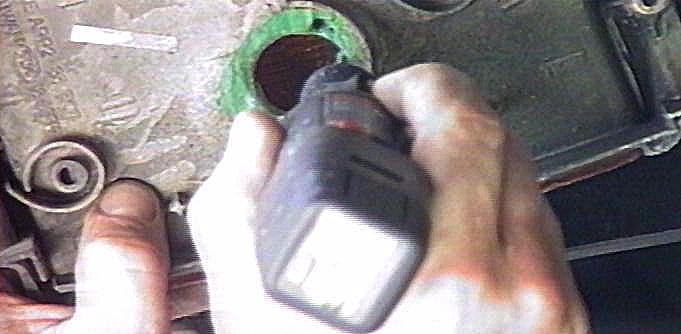
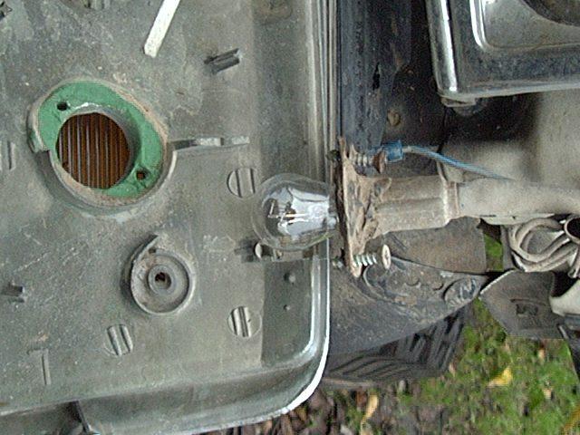
Here's the finished assembly. In the above-left picture, note the epoxy putty around the lamp hole, the silicone around the socket base, the two screw holes for attaching the socket and the new socket and bulb. In the above-right picture, note the upper screw has the ground connection tied to it as this socket relies on the base for ground.
The new turn signal location is much more visible than the stock signal, especially to the side. The larger reflector and bulb also make the signal a lot brighter. With the lens up higher, it stays much cleaner. The wires are tucked up inside the fender out of harms way. Finally, there's only one bulb to keep track of instead of two (and its the same bulb used in the tail light). This project should take 1-2 hours to complete.
Notes:
- This is a non-reversible modification. Once you start cutting, its too late to go back.
- To change the bulb; unscrew the metal plate and pull out the socket.
-
Be sure to thoroughly test the lights after assembly. Check turn signal
operation with and without the parking lights and headlights on. Make
sure the rear lights still work, too.
Turn Signals in action
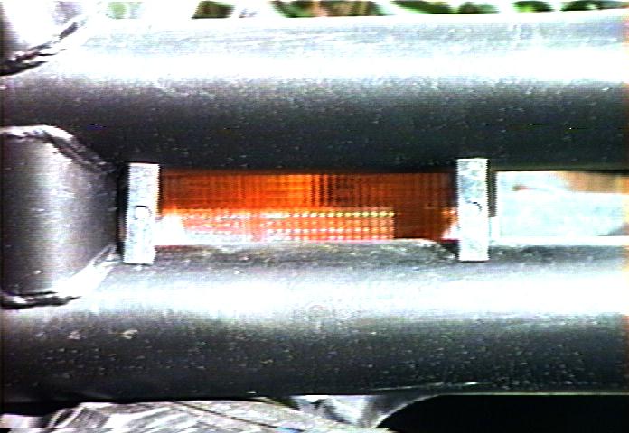
Here is how the combined turn signal/parking light works. In this case, I have the parking (side marker) lights on plus have activated the turn signal. And you can see that the side marker light stays on (the low wattage filament in the 1157 bulb) and the brighter turn signal filament blinks on and off. So one light, two functions! Note the the lens illumination is much more uniform than captured by the camera, which only shows a pin-point of light. This is also why I chose to use a filament bulb instead of the popular LED retrofit, as the filament bulb throws light more uniformly around the surface of the lens.
[Return to the top of this page]Cost:
  2  Universal light sockets    $8
  2  1157 parking/turn bulbs     2
  1  Epoxy putty                 5
  --------------------------------
                               $15
Rating:

-
A couple of side benefits of this modification:
- The first is that the 1157 bulb used matches the one in the rear brake/parking light socket. So as far as carrying spare bulbs, that eliminates the need for a different bulb type in the parts box.
- The second is that you'll now know where the wiring for these lights are and how they are connected. Armed with this knowledge, projects like adding fog and driving lights are simplified. For example, when I installed fog lights, I wanted to make sure the fog lights could be on at any time other lights were on and would go off when lights were turned off. This was easily accomplished by powering the fog light relay from the parking light "hot" wire, i.e. the one that isn't common with the turn signal. Since I clearly labeled the connectors and wires, it was a simple matter to tap into this line to get switched power for the relay.
More Information:
Here is a slightly different version of this modification on a 2nd gen 4Runner:
If you would rather modify the existing side marker light housing for a different bulb, here's another way to accomplish a very similar mod and this one even works in conjuction with the stock turn signals (it is for a VW, but the concept is similar for any vehicle):
[Return to the top of this page]LED Bulb Retrofit / Flasher Relay Modification:
I finally found a set of LED 1157 bulbs that seem to work well with the modified housings:
https://www.superbrightleds.com/
These bulbs throw light out the end as well as around the side and at 3W are brighter than the incandescent bulb. They're also availabe in an Amber and Red color which I prefer. This is in case I break a lamp housing on the trail, I'll still have the proper colored light to avoid the dreaded "fix-it-ticket" on the way home from a run. One issue with the LED bulbs is the high speed (hyper) flashing. This is due to the lessened current of the LED bulb making the stock flasher relay "think" there's a burned out bulb. One option is to get a "heavy duty" flasher relay, but finding one that matches the 3-pin pattern of the Toyota relay is hard. You can also add load resistors to the turn signal circuit. I once did this using a trailer wiring adapter and wiring the load resistors, 6 ohm - 50 watt, in parallel with the left and right turn signals. But the easiest fix is to modify the Toyota flasher relay by breaking the load sense circuit. You can cut one lead of the small resistor shwon below or use a soldering iron and heat up the solder joint and lift the lead out of the PCB. Now the flashing rate is the same no matter the load. Realize you'll no longer have a "bulb out" indication.
> |
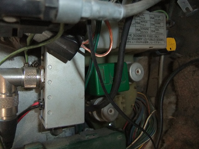 |
| Flasher relay modification - courtesy IH8MUD.com | Flasher Relay location - driver's side kick panel below fuse panel |
The IH8MUD forum has a related thread and apparently the source of the image above:
Here's another option, make an adapter that plugs into a trailer light connector with a pair of 5W power resistors in parallel with the turn signals.
[Return to the top of this page]
![]()


Visitor # 78606 since 28.AUG.2001
[Last updated: 26.September.2023 ]