Toyota 22R-E Engine Build-up
Contents:
[Return to the Cheap Tricks main page]Introduction
The Toyota 22R-E engine in my 1985 Toyota 4Runner is adequate for most uses. However, as I lifted it, added bumpers, winches, larger tires, etc. I found it got progressively slower and slower. The vehicle had over 200,000 miles on it, the engine was an ATK rebuilt unit, but it still seemed slow to me.
My first glimmer of hope came one weekend when I decided to whack off the stock muffler (looks like its big enough to fit on a bus) and replace it and the restrictive tailpipe with a 2" bullet-style muffler and 2" tubing I had laying around in the garage. I found this simple mod made nearly a 1-gear difference in hill climbing and prompted further investigations. It also added a nice tone to the exhaust note and got the tail pipe up out of harm's way.
[Return to the top of this page]Exhaust:
When I changed the muffler, I looked in the tail end of the catalytic converter (my first time owning a cat-equipped vehicle) and it "looked" OK. The bolts in front were rusted on solidly, so I didn't look at the inlet of the cat. I had thought about adding an exhaust header and waited for a 50-state smog-legal unit to come on the market. Finally LC Engineering came up with a CA-legal header for the 22RE and after about a year I ended up getting one. The LC header bolted right up without too much trouble. I re-used the factory manifold block off plates over the 22R air injection ports:

I did have to cut off the rusted bolts holding the catalytic converter to the stock downpipe. Once open, I was amazed to find the cat was 95% plugged. A 1" dia section in the middle was open but the rest of the matrix was totally plugged. So, I picked up a new aftermarket (Maremont) cat. Unlike the unit I was replacing, which had fully welded flanges, this one had the exhaust tubing flared out over a loose flange. I couldn't get a good seal so ended up TIG welding the flanges to the exhaust tubing and ground it all flat for a better seal. With the header and cat, I was faced with a terribly loud exhaust, not quite open headers, but close.
So, time for a new muffler, a bit of research found that the new Flowmaster mufflers have decent sound deadening with low restriction and a quick on-line order from Summit Racing resulted in a shiny new Flowmaster muffler on my doorstep 3 days later. Hooked it up and found it gave a nice exhaust sound and the new found power was great. I got almost another 1-gear improvement in hill climbing.
- Cost:
- I paid about $250 for the LC header, purchased from a 3rd party, Flowmaster muffler was about $90 delivered and I had all the other exhaust tubing and fittings left over from other projects.
EGR:
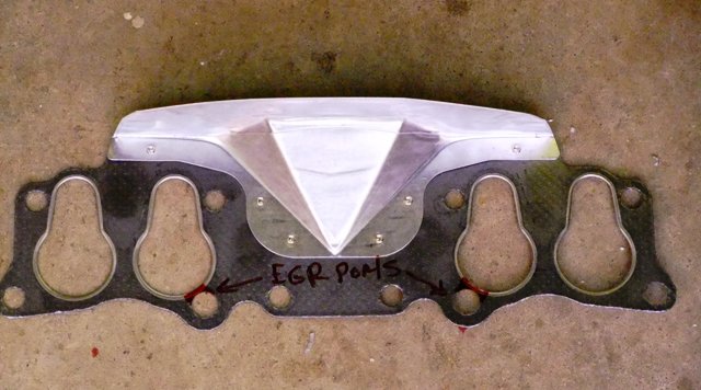
One issue I ran into later on with my LC header was when I had to start doing the dyno tests for CA smog every 2 years. I found I had trouble passing the NOx tests and part of the issue I tracked down to the EGR ports in the head and how exhaust gas got into them from the header. It turns out there are two small round ports to the bottom side of the #2 and #3 exhaust ports that send exhaust gas back through an internal passage in the head to the EGR cooler that bolts to the rear of the head. On the LC header, there are little notches milled into the header flange to send exhaust gas to those two ports. But I found two problems with that design that caused flow restrictions due to the small depth of those passages.
One was that the header tube weld bead protruded into that milled notch. So I took the time to grind down that weld bead and even round over the inside edge to aide gas flow into that EGR port. Here's a web post describing how well this worked. A Dremel with a small grinding stone or a die grinder or even a small round file would work. All you're trying to do is round over the weld bead along the short section where the recess is for the EGR port.
The second issue was the thin web of gasket material between the main exuast port and the EGR port. Over time, carbon builds up on that gasket and makes it thicken and intrude into the gas passage. So I simply took a new gasket and cut out the web of material between the main and EGR port, shown in red below. The basic idea is to make the #2 and #3 ports have a larger opening. In the stock cast iron exhaust manifold, there is a dedicated gas passage cast into the manifold that takes gas from the exhaust runner back to the EGR port hole. But the way the LC header is set up, they rely on that small passage into the flange and thus there is no need for a gasket in between the two holes, as there is no contact between the flange and head at that point.

I spent most of one day cleaning and "porting" the exhaust gas passages from the header, back through the head, the EGR cooler and the EGR valve itself. I used a small gun cleaning kit it the solvent and small round brushes along with compressed air to blow out all the passages. Doing that dropped the NOx readings from just barely passing a smog check to having a somewhat comfortable margin. Realize that for EGR to work, it must dilute the incoming air charge with the inert exhaust gas. On a 22RE @ 3000 RPM, you're looking at ~65 CFM incoming air flow, you need to have some fraction of that volume replaced with exhaust gas for the EGR system to do it's job of lowering NOx.
On all 22R engines, this obstruction could result in lowered EGR function, which in turn can lead to higher NOx readings in the exhaust during a smog check. The way the EGR works is by recirculating exhaust gas back into the intake manifold. This dilutes the intake air with "inert" exhaust gas to dilute the intake air charge which reduces combustion temps and thus NOx creation. If you only have a tiny trickle of exhaust gas flowing back to the intake, it doesn't have much, if any, effect.
- Here's a video if yhou prefer that format.
On a later model 22RE engines, that have an EGR with built-in temperature sensor, this flow obstruction could result in a #71 CEL code being thrown. That code indicates that the temperature of the EGR valve body didn't reach a set temperature in operation. It's the hot exhaust gas flowing through the EGR valve body that heats it up in operation. Low flow of gas = lower temperature. How exactly the ECU "knows" the vacuum controlled EGR valve should be open is beyond me? Here is one work around for recurrent #71 codes.
I found the following in a Training Manual describing various versions of the Toyota TCCS (Toyota Computer Controlled System) engines. It noted that this is only on the "California" spec. engines (22-REC) and likely starting in the early 1990's:
-
EGR GAS TEMPERATURE SENSOR:
- This sensor is mounted in the EGR valve . It detects the temperature of the EGR gas. This sensor is composed of a thermistor, and it resembles the water temperature sensor or intake air temperature sensor . The signals from this sensor are used in the diagnostic system . When this sensor detects EGR gas temperatures below a predetermined level during EGR system operation, the Engine ECU judges that the EGR system is malfunctioning and lights the "CHECK ENGINE" lamp to inform the driver.
-
EGR CUTOFF CONTROL SYSTEM:
- This system actuates the VSV, which therefore causes atmospheric air instead of intake manifold vacuum to act on the EGR (exhaust gas recirculation) vacuum modulator. This shuts off the EGR to maintain drivability when the engine coolant is cold or during high-speed driving etc.
-
OPERATION
- The Engine ECU actuates the VSV, shutting off the EGR when the coolant temperature is below a predetermined temperature or when the engine speed is above a set speed (roughly 4,000 to 4,500 rpm), to maintain drivability . The ECU also actuates the VSV to shut off the EGR when the intake air volume is above a predetermined level or when the fuel cut-off function is on in order to maintain EGR valve durability.
-
There's also a mention of the ignition timing control system in the ECU uses inputs from the
TPS (throttle Position Sensor) and the engine speed/RPM to adjust the igintion timing during
EGR operation, known as EGR Correction:
- When the EGR is operating and the (TPS) IDL contact is off, the ignition timing is advanced according to the volume of the intake air and the engine speed to improve drivability.
On the earlier 22-REs, Toyota used a BVSV (Bi-metal Vacuum Switching Valve), that sat under the throttle body. It had coolant routed through it. When the temperature rose high enough, the valve would open and pass manifold vacuum through to the EGR modulator.
On the later model 22-REs, Toyota replaced that BVSV with an electrically controlled VSV (Vacuum Switching Valve). The ECU would monitor the coolant temperature, and when that was high enough, as mentioned above, it would send manifold vacuum to the EGR modulator.
Note, that in the above training manual excerpt, the EGR isn't actuated directly by this VSV. Instead, all it does is send a vacuum signal from the throttle body up to the EGR modulator. It's the EGR modulator that turns the EGR on and off. Now, it is true that the ECU can turn the EGR off by closing the VSV.
For proper EGR operation, and this lower NOx readings during a smog test, the EGR system has to be working properly. No clogged passages, all vacuum lines connected properly and even the fittings that those lines connect to have to be clear of deposits. Some tips I've found for lowering NOx readings are to retard the timing as much as I can get away with. Most smog techs I've run into seem the think the 22RE should have a vacuum advance distributor, so they look for that line to unplug for checking the timing. They don't seem to know about the timing jumper and I'm not going to tell them about it :). So I find I can retard the timing around 5 degrees and it'll look normal without the timing jumper installed. I'll also dump in a few gallons of premium gas into a nearly empty tank for the test. Then, drive the truck a good 30 mins, before the test and keep it idling while you wait to go in.
[Return to the top of this page]Camshaft:
TRD Level 1 Cam; installed
One day, I was looking around eBay and saw a new TRD Level 1 cam for the 22RE engine for sale. I put in a bid for a little under what I could get one from TRD for and lo and behold, I won the auction for $100. So, why TRD, when it seems to be simply a re-badged Crane cam? Well, TRD went to the effort to get a smog exemption sticker for the state I live in. After getting the cam, I saw the instructions recommended replacing the rocker arms, so that looked like it would run into some more money (about $200 or so). I decided instead to put up an LC Engineering rocker arm assembly with all new parts to save the hassle of tearing down and rebuilding my existing one. I was a good thing I had the new assembly on-hand as I noticed one of my stock rockers seemed to be running way off center (in other words my rocker was off its rocker:-).
TRD 20R/22R/22RE Cam Specifications:
| Level | Intake Lift |
Exhaust Lift |
Intake Dur. |
Exhaust Dur. |
Duration @.050 lift |
RPM Range |
TRD p/n |
Notes |
| 1 | 0.416" | 0.430" | 262° | 272° | 214°/224° | Idle- 4800 |
00602-13511-000 | 50-state Smog Legal, Low-mid range power, smooth idle, EFI compatible |
| 2 | 0.430" | 0.444" | 272° | 282° | 224°/234° | 1600- 5200 |
00602-13511-001 | Off-highway use, mid-range power, fair idle, EFI compatible w/ proper tuning, headers + perf. exhaust recommended |
| 3 | 0.411" | 0.458" | 282° | 292° | 234°/244° | 2000- 5700 |
00602-13511-002 | Off-highway use, mid-top end power, rough idle, will not work w/ factory EFI, headers, exhaust and head porting recommended |
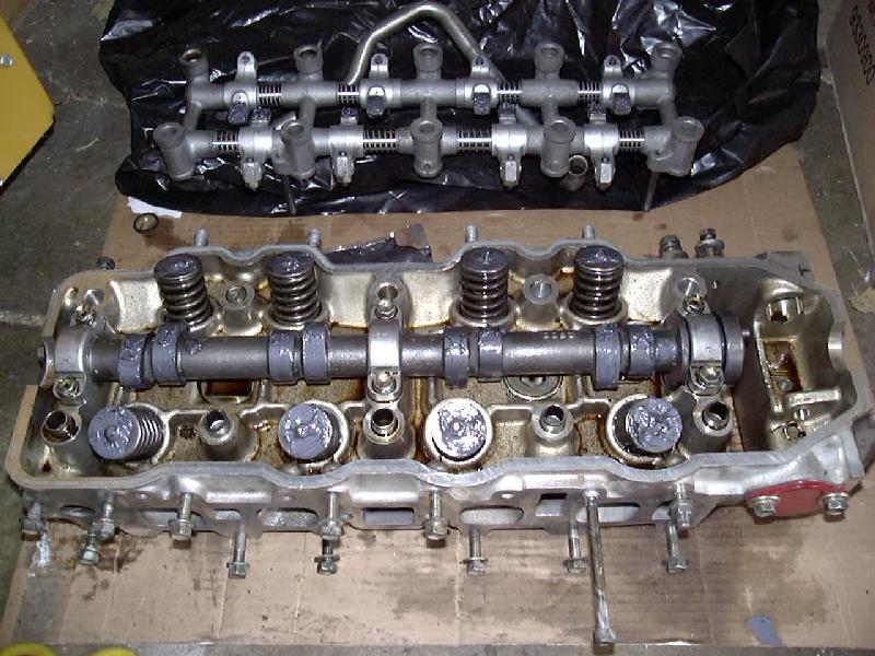
Also, in the above picture, you can see how I re-installed all the bolts I removed from the head back into their respective locations. This made it easy to remember where each of the bolts goes for re-assembly, as I had the head out for a few weeks while I was getting other parts ready. Also, you can use the picture as a reference to see how many bolts need to be removed to separate the intake from the head.
After setting the valve clearance, cold (0.007"-0.011"), I ran the engine at 1500-2000 RPM for about 20 minutes to break in the cam and rockers. After this, the valve clearance was checked again and set hot (0.008"-0.012"). I later found out the TRD cam should be set a little tighter than this, so I'll be re-setting it to 0.008" (intake) and 0.010" (exhaust) hot. I have been running w/ the looser 0.008/0.012" clearance for over 2 years w/o problems, but I'll try the tighter specs and see how it runs. (Note, I bought the cam "used" off eBay, it had never been installed but the box had been opened. Thus I had no information about its installation and used the stock FSM specs).
- Cost:
- I purchased the cam shaft off of eBay for about $100, they are $125 or so from TRD. I opted to replace the rocker arm assemby with one from LC Engineering. Cost was about $250-300. My old one was fairly well worn, so just replacing the rocker arms, as recommended by TRD, was not feasible.
- Difficulty:
- Installing the cam itself is easy, getting to it is harder. You do have to remove and re-install the head bolts and timing chain at a minimum. I removed the entire intake, exhaust and head as well. How hard the job is depends on what else you are doing at the time and what other issues you might run into. A Factory Service Manual for your year vehicle would be a very good reference and study the actual steps involved before embarking on this project.
- References:
-
22R
Valve Adjustment
- Timing Chain Replacement
- 22R Cam Installation Writeup
- Note: If you're experiencing random engine stalling when disengaging the clutch near idle, this may be a sign of exhaust valves that are too tight. Another sign of this is low manifold vacuum. This is caused by the valves not closing fully and allowing exhaust to be sucked back into the cylinder on the intake stroke. It's basically like EGR on steroids!
- Timing Chain Replacement
Cylinder Head:
Installing ARP Head Studs
When installing a new cam shaft, one option is to simply back off the head bolts, remove the rocker arm assembly, carefully unbolt the cam shaft bearing caps, swap things around and hope the head gasket holds while you get it all back together. I was originally planning to do this, but decided that since I was into the engine this far I might as well go all the way. It was recommended to me that replacing the stock head bolts with ARP head studs was well worth the investment. They have a number of benefits over the stock head bolts:
- They make head installation a lot easier as the studs align the head and hold the head gasket in place
- They are twice as strong (190,000 psi steel alloy) as the stock head bolts
- They clamp much better since the stud is loosely threaded into the block and the clamping torque is generated at the stud-nut interface rather than the block-bolt interface
- They are torqued in the factory sequence up to 80 ft.lbs. per the ARP instructions
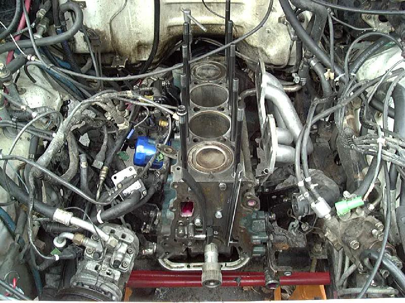
After pulling the head bolts, several came up dripping with oil or coolant. Putting bolts back into the block this way is not a good idea (the bolt may bottom out in the hole and give a falsely high torque reading) so pulling the head seems to be the only way to go. I cleaned out the bolt holes in the block with a cleaner then blew compressed air across to the holes to suck out the residue. Then I picked up a 12x1.25mm tap and chased all the holes for good measure. You can see 9 of the 10 studs in place as well as my tap in the remaining hole. For ease of installation of the head, you should leave the rear-most pair of studs out and install them after the head is in place. The remaining studs perfectly locate the head gasket and ensure the head is properly aligned when you drop it in place.
If you look closely at the front of the block, you'll see the DOA steel timing chain guides installed. My 1-2 year-old plastic guides were showing early signs of breaking down. The DOA guides look like they'll hold up a lot better than the flimsy factory plastic guides. The DOA guides are a piece of cake to install, just unbolt the stock ones and bolt up the new ones with the supplied hardware. I found I had to loosen the top bolts to get the (new) timing chain sprocket back on the cam shaft. After the chain was on, I re-tightened the guide bolts. A new timing set was installed (upper and lower sprockets and chain). Just align the "bright" links on the timing chain with the marks on the lower and upper sprockets (and double/triple check the alignment before bolting the timing cover back on).
A few tips on removing and installing the main crankshaft pulley:
- To remove the pulley, disconnect the ignition coil and put a 19mm impact socket (1/2" drive minimum) on a long breaker bar and jam the bar between the frame and steering box with the socket on the center pulley bolt. Then, hit the starter for a second or two until the bolt breaks free.
- To remove the pulley, I used a K-D Tools 2291 Steering Wheel/Crankshaft Pulley Puller which includes the M8-1.25 bolts to fit the pulley bolts.
- To re-install the crankshaft pulley, put the vehicle in gear, high range 4th or 5th gear, set the e-brake and put some blocks in front of the wheels (as well as behind). Then you can crank the bolt to the specified torque. Its important to use a high gear, not a low one, as the higher gear makes the e-brake more effective.
- Cost:
- The ARP head stud kit cost about $100 from Summit Racing. I also used a master rebuild gasket set from Toyota that was about $200. The head studs could be installed w/o removing the head, but I felt the risk of a head gasket leak was not worth the small cost savings. Same for the cam shaft install, could be done in place but was much easier with the head off.
Fuel Injectors:
When I pulled off the intake air plenum, I noticed a very think layer of black goo and carbon built up on everything. I also noticed what looked like raw gasoline in one or two of the intake runners, and figured that was not good. In fact, when I cracked the fuel injector feed lines to relieve the residual pressure, there was none, it had all leaked out the injectors. So, I pulled all 4 injectors, boxed them up and overnighted them to RC Engineering to work their magic on. Three days later, a box arrived with 4 brand new looking injectors and the following report:
| Injector | Before cc/min |
Before Pattern |
After cc/min |
After Pattern |
| 1 | 178.4 | Dripping | 184.1 | Excellent |
| 2 | 171.5 | Fair | 182.9 | Excellent |
| 3 | 177.9 | Good | 183.5 | Excellent |
| 4 | 179.0 | Good | 184.0 | Excellent |
One important note on the Toyota fuel injectors. They use both an o-ring and a separate hard insulator/spacer to install. If you pull the injectors and send them out for cleaning, be sure to remove and keep the insulator piece for use when you re-install the injector. RC will send you new o-rings, they also are included in the master overhaul gasket kit if you are doing an engine rebuild. But, you won't get the spacers and without them, the injectors will not seal properly in the fuel rail and head.
- Cost (ca. 2000):
- About $24/injector plus shipping for the injector rebuild.
Cruzin Performance is another source for cleaning/rebuilding injectors, as is Witch Hunter.
While I had the fuel injector rail out, I noticed that while the body was made of cast aluminum, the end cap was a plated steel material. I wanted to install a fuel pressure sender for a gauge on my dash. So I drilled and tapped a hole (1/8" NPT as I recall) and screwed in a brass thread adapter. I then soldered that in place since with wall thickness of the end cap didn't offer much thread depth for a good seal. Then I screwed the sender (0-100psi) into that and ran some wires to the dash. This has proven to be a very useful troubleshooting tool and I added a switch to the pressure gauge and can connect it to my on-board air pressure sender as well.
[Return to the top of this page]Results:
So how does the engine run after all this work? One word, GREAT!
My goals in the upgrade was to have at least the same driveability with 4.88 gears as I had with 5.29s (running 33" tires), and since I live in the state of California, I wanted it to remain smog legal, thus the choice of certain 50-state smog legal parts.
I think I met both goals, the truck runs easily on the freeway, 65-75 all day long, throttle barely pressed, before 70 required full throttle. I also gained about a 1-gear increase in hill climbing at speed. In fact when I ran briefly with 5.29s, I noted a 2-gear increase, but after losing the 13% gear ratio change, it was back to 1-gear.
The engine passed its first smog check fine, emissions were somewhat higher than before, but under the limits. The only downside so far is that gas mileage has dropped. I haven't had the time to work on that, but I think I can get that back up to where it was before. One interesting thing I noticed was that before the buildup, I used to get 19-20 MPG running 33x9.50 radials and ~15 MPG running 33x15.50 bias ply Swampers. Now I get 15-16 regardless of the tire. About the same time I did install a 3" body lift and dropped the front spring hanger 2.5" (netting 1.25" of lift), which no doubt increased the wind drag. I did one drive in Oregon at 55 MPH and observed about 20 MPG on one tank. After a few years operation and fixing several minor issues I've been able to work the highway mileage up to around 18 MPG at high speed (65 and above) and can hit 20-22 at slower speeds (55 and below). Some of the issues fixed included changing out the old, stiff fan clutch for a new Aisin unit, repairing several vacuum leaks by replacing all the original rubber vacuum hoses with new silicone hose, etc.
To monitor the engine function, I installed an Air/Fuel gauge that takes an input off of the engine's O2 sensor (Nordskog brand) and also run a fuel pressure gauge (sender plumbed into the back of the fuel injector rail). Both gauges seem to indicate everything is working properly. No lean conditions are reported, no fuel pressure drop. And this is all without touching/tweaking any of the EFI components. AFM is set to it's factory calibration, no "calibrating resistors" in the various engine/air temperature senders, etc.
Things still to be done are to reset the valve clearances a little tighter, and possibly look into degreeing the cam with an adjustable cam gear.
[Return to the top of this page]References:
- Here is a handy step-by-step description of changing the timing chain
- A Toyota Factory Service Manual is an invaluable source of information
[Initial creation: 28.JAN.2000]
Visitor # since 18.MAY.2002
[Last updated: 29.August.2025 ]
Copyright© 2000-2024 Roger Brown - All Rights Reserved, Content of this page may not be reproduced without the permission of the author