Crossover Steering Installation
Contents:
- Introduction
- IFS Power Steering Box
- Double Arm Crossover Steering
- HySteer Crossover Steering
- Front Spring Hanger Drop
Introduction:
When I first purchased my 4Runner, it had the stock push-pull solid axle steering setup. With the stock springs, it worked like a dream. After I installed 3-1/2" lift springs and a dropped drag-link, the steering was not so great. I spent a lot of time tweaking things, I found by over-tightening the adjustable drag link ends, it was improved somewhat. After finding my front springs caused the stock spring shackle to hit the frame under full compression, I had to go to longer shackles. This made the steering even worse, as the caster angles were off. I determined a 3° shim would bring me back close to stock, this made things better again. However, the shim tilted the axle and now my stock torque rod was binding up. I switched to an adjustable torque rod and this problem improved. However, with 33" tires, I had the notorious tire rubbing the back of the wheel well problem. Only real solution is to move the tire (and axle) forward to gain more clearance. While it is possible to do this sort of modification to the stock steering, I was tired of fooling with it and scheduled an appointment with All Pro Offroad to install their crossover steering kit...
[Return to the top of this page]IFS Power Steering Box:
First thing to go was the stock solid axle power steering box. This box has a steering shaft that extends out parallel to the axle with a pitman arm that rotates front to back (a.k.a. push-pull steering) and has a drag link that connects it to the steering arm (a.k.a. J-arm). The crossover setup utilizes an IFS power steering box, where the steering shaft is orented vertically and the pitman arm stings side to side, i.e. crossover steering.
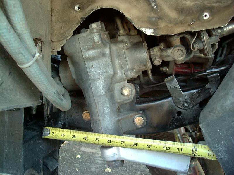
In the image above, you can see how the box is installed to the outside of the frame. It is important that it be pushed as far forward and as high on the frame as possible. This insures maximum clearance. In the photo, the tape measure end is attached to the back side of the body mount bracket. The forward bolt is approx. 4" behind this bracket. If the steering box is located too far back on the frame, the draglink and tie rod may hit each other under compression.
Steering Box Reinforcement:
So with a freshly rebuilt axle, it was time to do some wheeling. One of the first trips was to the world famous Rubicon trail. First day we went down the slabs from Loon Lake, through the alligator pit and pinch rock and in one place I got hung up trying to squeeze between a couple of big rocks. As I tried to push through, I heard my fan hitting the shroud, getting louder the harder I tried to turn the steering wheel. After passing that obstacle, we soon came to Walker Hill. I noticed my steering felt a little sloppy and by the time we crested the top of the hill, I knew something was wrong. I pulled over and saw the sleeves for the steering box mounts had pulled loose from the inside of the frame and a huge gaping hole remained around one of them. The only thing holding the box in place was the top bolt/bracket and the one remaining bolt was twisting at the head. I quickly scrounged up an old spring shackle plate out of my parts box, and re-inserted the torn-loose bolt through the plate and cranked it down good and tight. The field repair held for the rest of the trip, including my first trip through the Little Sluice and the spectacular drop into the Big Sluice.

After getting home, I surveyed the damage and it didn't look to good. I found a piece of 3/8" plate that was just long enough to span the two lower bolt holes, drilled it to match. Before installing it, I decided I should do something to reinforce the damaged inner frame rail. I used up about a half dozen welding rods filling in the huge gaping hole in order to support the sleeve and give the backing plate something to rest against. Then after bolting up the plate, I welded it to the frame along the bottom edge, and purposely not welding the ends to the frame to avoid creating a stress point at the joint.
Silence is golden, no more squeaking, no more slop in the steering. I would highly recommend anyone installing an IFS power steering box on a solid axle truck install a similar plate. Sleeves alone won't stand up to hard wheeling.
Later, I decided to brace up the outside of the frame as well. I used some 1/4" steel plate to fashion a brace from the front of the steering box and back along the frame to strengthen up that area. This also helped to move the box out away from the engine and gave the steering shaft additional clearance where it passed the 160A Premier Power Welder alternator that is larger in diameter than the stock alternator:
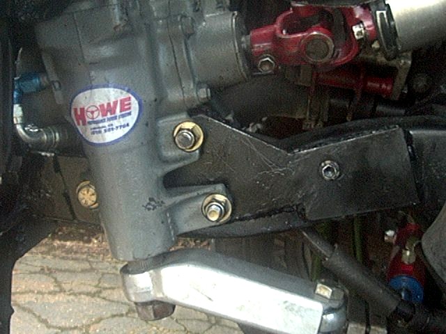 |
| Outer Frame Reinforcement |
[Return to the top of this page]
Extending Steering Shaft:
One of the side effects of having the steering box moved as far forward as possible is that the steering shaft has to be extended. Combined with the body lift on my 4Runner, my shaft was pulled out about as far as it could be. With so little engagement of the telescoping section, it was fairly loose. I could have drilled and bolted those two pieces together or even welded it, but instead, I reasoned that adding a spacer at the base of the shaft would shove the two sections farther together and that would tighten things up. So I installed a ~2" steering shaft extension under the rag joint, as shown below:
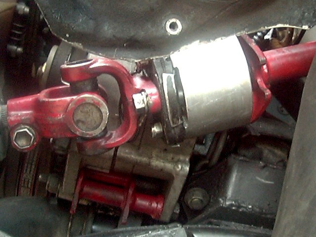 |
| Steering Shaft Extension |
The extension did the trick, steering shaft is nice and tight and no need to make any permanent modifications to it. This part is available here in 1" and 2" versions.
[Return to the top of this page]Double Arm Crossover Steering
I arrived first thing Monday morning and by noon, the stock steering box, torque rod and bracket were removed and mounting holes for the IFS steering box were drilled. Later, sleeves were added to the lower two holes through the frame and a bracket for the upper mount were all welded in place. The stock steering arms were removed, the driver's side (J-arm) was modified by cutting off the drag-link end and a pre-fabricated double arm was used on the passenger side. A Marlink heavy duty tie rod was installed in place of the stock tie rod and a used IFS power steering box was installed. After hooking up all the parts and doing a quick alignment, I was on the road by the end of the day.
A week of wheeling was in store in the Southern California desert. I met Terry Johnson and Randy Burleson and we headed east from the AllPro shop in Hemet, CA. to start our adventure. Unfortunately, Randy had to return to work to handle some urgent problems, so Terry and I headed off to Joshua Tree NP, Johnson Valley and finally Santiago Canyon. The steering worked great for the trip and even without a steering stabilizer, it was rock solid and it handled like a sports car (albeit one on 33" mud tires and 4" of lift). Next trip was to Panamint and Death Valleys a month later. I started hearing a creaking sound from the front end. Upon returning home I found the nut holding the pitman arm to the steering box was a bit loose, so torqued it and the other bolts down. This seemed to quiet the strange noise for a while, anyway. It would return, and I'd torque the fasteners, until about 5 months later, no amount of torquing would silence the noise. I figured it might be the steering knuckles making noise and a leaking axle oil seal (and a coat of gear oil covering the side of my 4Runner) prompted me to rebuild the front axle.
[Return to the top of this page]HySteer Crossover Steering:
So, I'm all set with my crossover steering, all the kinks are ironed out, why mess with a good thing? One day, I stumbled upon a deal too good to pass up, a used HySteer crossover kit. So, I snapped it up in an instant. Actually, at the same time, I was toying with the idea of swapping my front differential over to an FJ-80 high-pinion unit, which would raise the front drive shaft about 4". This would get the back of the axle more clearance, but what about the front? So, that's where the HySteer comes into the picture.
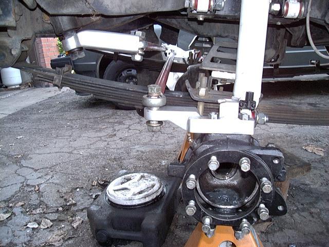
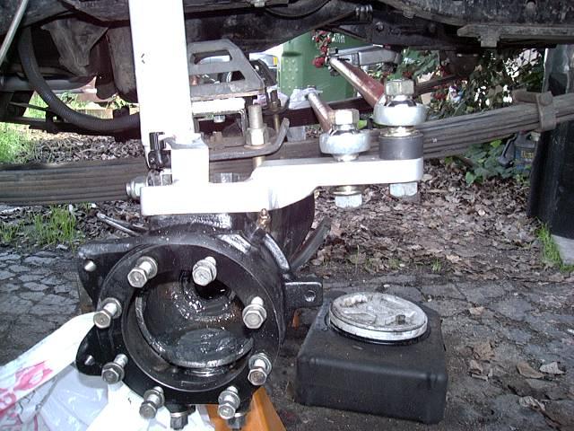
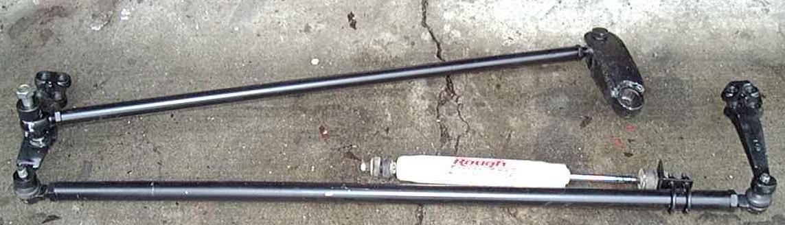
It took me a few months to get around to installing the HySteer kit. After breaking both Marfield joints at Panamint Valley Days, I had the axle torn apart, so why not take the plunge. Above, you can see the driver and passenger side steering arms with the crossover drag link and tie rod connections. This is the original AllPro HySteer kit and it looks massive. Clearance over my front springs is rather tight in this picture, with 7 leaves and a 3 degree shim (fat end in front). I had been planning on dropping the front spring hangers ~2" to correct the front caster angle caused by the 2" longer spring shackle, which will let me remove the shim and gain 1/4" of clearance. Then with the additional lift of the dropped hangers, I'll probably remove a leaf or two to drop my ride height back down and thereby gain another 1/4" of clearance, which should work great (more on this later)...
[Return to the top of this page]
Steering Stabilizer Installation:
Another issue encountered with the HySteer system is where to mount a steering stabilizer. I ran mine w/o a stabilizer for a month or so and while 99% of the time it is OK, especially with the continuous wheel balancers smoothing out the front wheels, it is in turns and when hitting rough spots int he road, that unexpected oscillations can occur in the front wheels. It is just this sort of thing that a stabilizer (basically a shock absorber) is good at dampening out. I've seen some owners mount the stabilizer off the frame and connect it to the drag link. A problem with this approach is that the road shock comes up through the tires and wheels to the steering knuckle, steering arms to the tie rod then to the drag link. By placing the stabilizer directly on the tie rod, you can help prevent the vibration getting farther into the system. The factory stabilizer bracket is located too low to be of use, so I opted for a different mounting option:
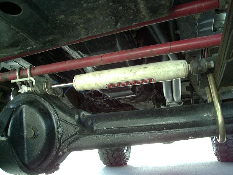
I fabricated a bracket from some 1/4" steel bar, drilling a hole to accommodate the stabilizer bushing, then welded that to the top-mounted u-bolt plate on the driver's side. Then, I attached a right-angle bracket with small u-bolts to the tie rod about in-line with the differential housing. I set the length to avoid hitting during steering motions. I found the tie rod moves approx. 6.5" lock to lock and the Heckethorn stabilizer I'm running has about 8" of travel. I had previously trimmed one end of the mounting stud down and it just barely clears the spring leaves behind the bracket. In a thousand miles of driving, both on and off road, its worked perfect, up and out of the way.
[Return to the top of this page]Spring Hanger Drop:
After pulling out the 3° shim, the drag link clearance was OK. But, I was still running about 3" tall bump stops to keep the springs from compressing into the pitman arm (darn those soft springs:-). So, I pulled the front spring hanger pins and lowered the axle for a look-see:
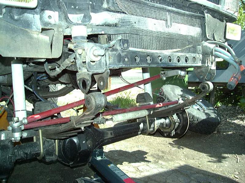
I settled on a 2-1/2" drop and a bit over 1/2" forward from stock. This leaves my 5-1/2" long spring shackles vertical at full droop, brings the axle to about the original angle, drive shaft angle is good (a bit above level), time to start cutting... I had found a few designs on the net for front spring hanger drop brackets:
I took the best aspects of the above two designs and modified them to suite my needs. Since my bumper is mounted directly to the frame (for added strength) I needed to allow for it to be re-mounted after dropping the springs. Like Jay, my weapon of choice was 2-1/2" x 0.125 wall square tubing. I used 3/16" x 4" flat stock for the rest of the assembly.
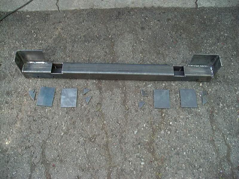
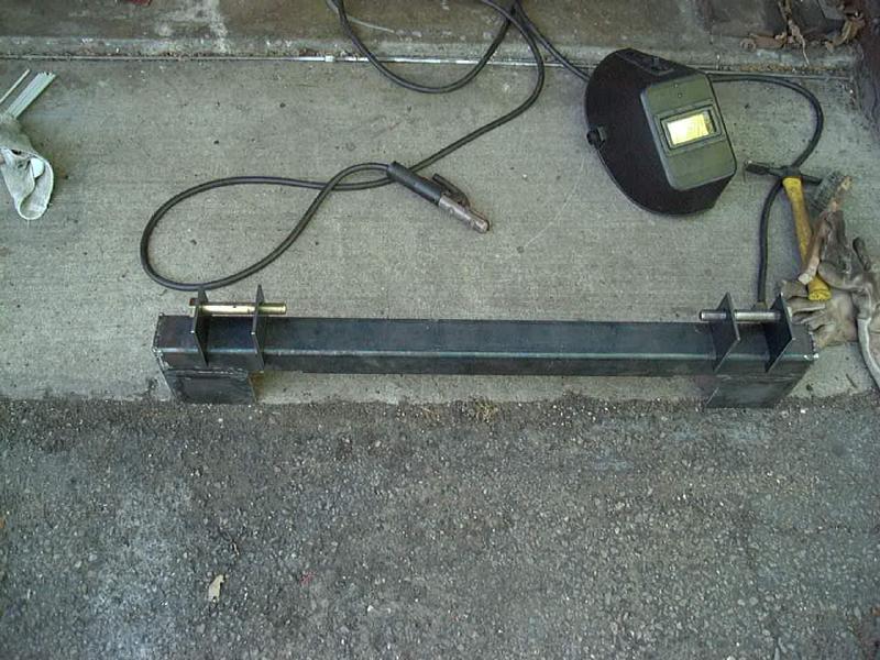
The main tube was cut 3/8" shorter than the inside of the bumper mounting brackets (that I didn't use originally to mount the bumper) so that I could attach vertical brackets to remount the bumper higher if needed. I notched the tube 1" deep for the spring hanger plates. I also notched the other side of the tube to fit over my 3/8" bumper mounting brackets, which are bolted to the tow hook holes. I used 18mm bolts from my old Downey Rubicon spring shackles, instead of the stock hanger pins. All parts were arc welded using 7018 rod. It makes a very nice looking bead and is very strong. I find it works best on DCEP.
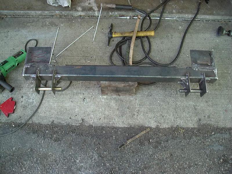
After cutting off the stock spring hangers (that's the point of no return!) I clamped the bracket to the frame to check the fit and alignment. I found I needed to add a piece of 3/16" stock across the main cross member to fill in the gap where the side rails meet it. I used a full-width piece, 4" wide, and then welded it to to stock cross member as well as to my new cross member. I also welded the new cross member to my bumper brackets and welded those brackets to the frame along their length. I also drilled holes for my old 3/4" bumper mounting bolts (which pass through the body mount brackets, to pass through to the bumper. This will allow the bumper to clamp the new cross member in place, keeping everything nice and solid.
(before)
(after)
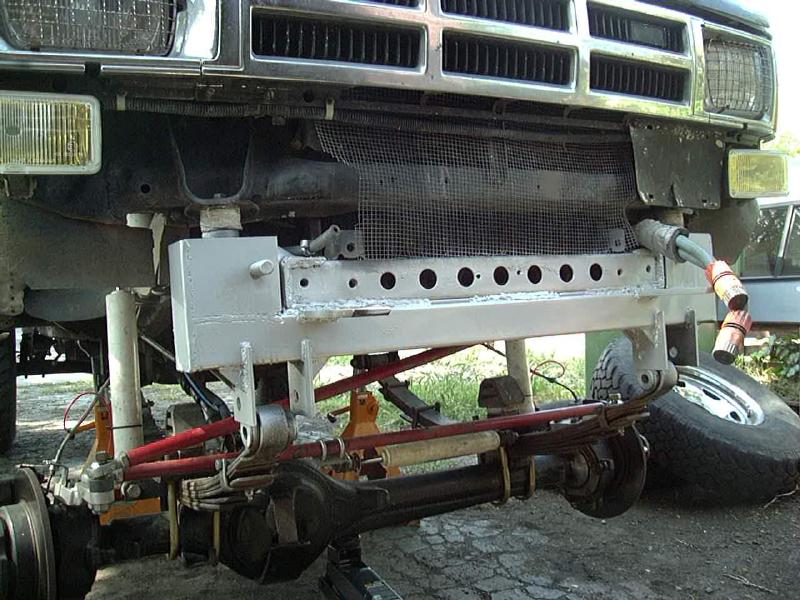
(clearance)
So, what did all this work accomplish? Above, you can see the before and after shots, above. Before I had about 2" of clearance at the pitman arm and bump stop (bump stop set very high to keep the springs from hitting the pitman arm). Afterwards, I have over 4" at the pitman arm, and since the whole spring/axle assembly is tipped down, I can drop my bump stops substantially to allow for more travel. Once I get the bumper re-attached, and do some fine tuning on my long travel shock setup and brake lines, I'll be ready to give this thing a real test. This modification (along with the use of stock rear springs) pushes the axle forward nearly 2-3/4" from stock, which is about the limit of the AllPro crossover steering, as pictured above. At full droop, the drag link sits directly above the tie rod, but moves back to clear it by about an inch at full compression. My front tires should now be well away from the inner wheel well, making room for 35's in the future. My long travel front shocks were designed with this modification in mind and they easily accommodate both the relocated axle and the additional travel. In fact, I may finally be able to go with the Rancho 9012's that I originally designed the system around (that will then give me nearly 19" of vertical shock travel, I think I can use at least 16" of that).

After a few trips, it was evident that the exposed hangers sticking out front were rock magnets. I kept having to straighten out the bent ends and decided to finally address that issue. I bent up a length of 1/4" steel plate to wrap around the front of the hanger and welded it in place. I also used this plate as an attachment point for my tow bar, so a pair of 1/2" heavy nuts were welded to the inside of each plate. After a recent trip over the Dusy/Ershim trail, the boxed in hangers really did their job, lots of rock dust and scrapes, but no damage.
[Return to the top of this page][Return to my Cheap Tricks page] [Author: Roger Brown] [Initial Creation: 03.FEB.2000]
Visitor # 97484 since 30.OCT.2003
[Last updated: 10.March.2022 ]