Toyota/4x4 - Motor/Tranny Mount Spacers
After 25 years in operation, it's time to close up shop and move on to other adventures. Thanks to all the loyal customers over the years that helped to make this all possible. The web site will remain live.
![]()
Contents:
- Introduction
- Motor Mount Lift Spacers
- Transfer Case Lift Block
- Other Transfer Case Lift Options
- Contact Info.
Introduction:
While Toyota 4x4 engines are typically mounted high enough so that dragging oil pans is not typically a problem, there are some benefits to raising the engine and thus the entire drive train on a Toyota truck. The most common part that drags on Toyota 4WD trucks is the transfer case cross member. In stock form it is a box cross-section and hangs nearly 4" below the transfer case itself. It is not built to take a lot of abuse and once the fairly thin steel box begins to crush, it loses most of its strength. There are a number of low-profile cross members on the market to address this problem, but even going this route leaves the transfer case hanging well below the frame rails. The transfer case already rides up close to the transmission tunnel, so lifting it very much is not a viable option. If you have dual transfer cases, the rear-most case often is left hanging unprotected behind the cross member.
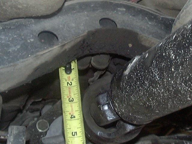
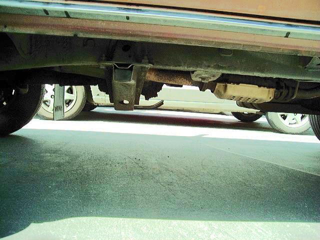
However, by installing a body lift to gain clearance, the drive train may be lifted up in the frame by an amount up to the height of the body lift. To lift the drive train, you must raise the motor mounts as well as the transfer case cross member, and most likely the "horse collar" cross member on the frame, depending on vehicle type and configuration. On most Toyota 4WD short wheel base trucks, it should be possible to raise the drive train about 1.5" without hitting the horse collar cross member. On the Extra cabs, you can probably do 2"-3" without trouble. You can simply measure the vertical clearance between the rear drive shaft and the cross member, allowing some room for movement under load (see picture below). If you have dual transfer cases and/or a reaf CV-style drive shaft, then you may need to raise that cross member even without a drive train lift.
However, there are other parts of the body/cab that can interfere with raising the drive train up higher. The best way to check for clearance is to unbolt either end of the drive train (i.e. the motor mounts or the t-case mount) and then use a floor jack with wood blocks to raise one end of the drive train up until it hits the floor of the body/cab and then measure the clearance between the motor or t-case mount and the frame or cross member. That distance would represent the highest you could possibly raise the drive train up, but be sure to allow some room for drive train movement under load. Since the engine and t-case are mounted atop rubber mounts, they can move around a fair bit in response to the torque applied to the drive shaft and more so in lower gears.
I did this very project on my 22RE-equipped 4Runner, lifting the body 3" and the drive train 2". I designed some bolt-on motor mount spacers and then used the Front Range Offroad Fabrication transfer case cross member and skid plate to accomplish the lift. I gained about 5-6" under the transfer case, replaced my sloppy stock transfer case mount and reduced the need for extensive modifications due to the 3" body lift. Since I had been running a 1" body lift before, I had set the radiator and shift levers to work at this height. So, my new lift (3" - 2") resulted in an identical 1" relative body lift off the drive train. It is still 3" off the frame, so things like steering and brake lines were modified. As can be seen in the image above, there is now about 1.5" of clearance above the drive shaft. Before the 1" (relative) lift, I had 1/2" (at rest) but under the stress and twisting off off-road use, that gap went to zero and let the CV hit the crossmember. So, you need to have at least 1/2" and better 1" of driveshaft clearance at rest to avoid contact.
Raising the engine had a side benefit when I later installed hydraulic-assist steering. With a high-steer (tie rod over the springs) setup, the hydraulic ram is mounted on top of the axle and the hydraulic lines are above that. I find I just barely have enough room to clear the hoses with the oil pan with the 2" drive train lift.
So after doing all the design work and tooling needed to make my own blocks, I thought I would offer my spacers to others interested in this modification. In fact, using my spacers and a BudBuilt cross member, it should be possible to do most of this project in a bolt-on manner. Generally, most Toyota trucks can take a 1-2" transfer case lift without moving the horse collar cross member. If you have dual transfer cases, a rear CV drive shaft, or a shorter wheelbase, then relocation may be needed, which requires some cutting and welding, but results in a raised gas tank.
Motor Mount Spacers:
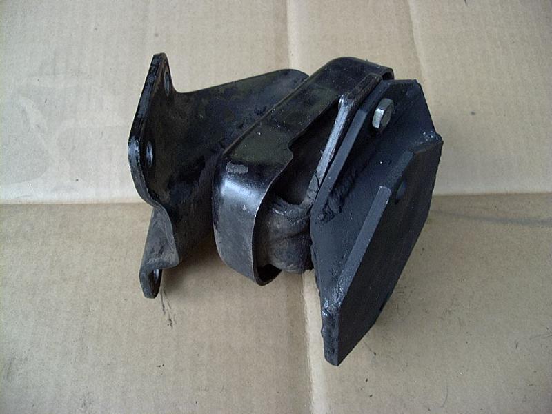
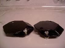
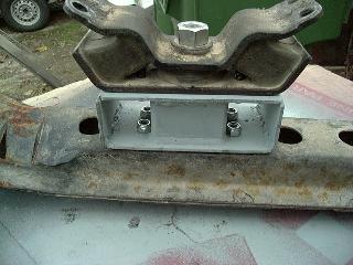
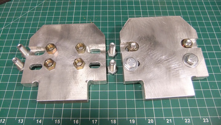
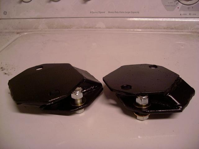
Pictured below are examples of a 2" motor mount spacer. To the lower-left, is the spacer installed on a stock motor mount (removed from the engine for clarity). To the lower-right is a 2" spacer installed between the frame and the stock motor mount. An advantage of this style of mounting is that it maintains the original engine-mount orientation. It also does not increase the load on the motor mount itself, as no added leverage is created.
 |
 |
| Motor Mount Spacer on Motor Mount Bracket | Motor Mount Spacer and Bracket installed |
The motor mount spacers can be made in heights from 1" to 3" that fit the stock Toyota 4- and 6-cylinder motor mount bases. New mounting hardware is supplied to attach the spacer the the frame bracket. Then the stock hardware is used to attach the motor mount to the spacer except with the 1" - 1.5" spacers which include new hardware all around. The spacers are made of 3/16" steel plate with angle-cut 2" square tubing - fully welded or machined billet aluminum construction.
- Do the spacers include new motor mounts?
- What about raising the transmission higher or lower than the engine?
- What about vehicles with 2-piece rear driveshafts?
- What abount (coil sprung) 2nd gen 4Runners?
- How is the lift height measured?
- How long does it take to fabricate and ship the spacers?
- Will my drive shaft need to be lengthened and/or will the shaft handle the increased angle?
- How high can I lift my drive train?
- Are there any considerations when installing these spacers along with a body lift?
- Which version should I order?
- 1. Do the spacers include new motor mounts?
- Motor mount shown above for illustration purposes only. The motor mount spacer kit is just that, spacers only, the motor mounts are not included. The spacers are compatible with stock and after market motor mounts. If running stock motor mounts, you might consider chaining the motor mounts if you take the truck off-road a lot.
- 2. What about raising the transmission higher or lower than the engine?
- While it can be done, the added angle applied to the motor mount will put it under some stress. An inch or so height difference between mounts is probably OK, but 2"-3" difference (front-rear) would likely be too much. I preferred to keep my engine and transmission level, so both ends are raised 2". Also, note that raising one end or the other a different amount will result in angle changes at the transfer case output flanges, which may affect drive shaft alignment and cause vibrations. And raising the engine and transmission equally will keep the exhaust level, minimizing/eliminating modifications required to that component. Also, the factory setup has the rear of the engine angled downward a few degrees to help drain oil out of the back of the head back into the oil pan. So it is always best to raise both the engine and transmission an equal amount.
- 3. What about vehicles with 2-piece rear driveshafts or coil sprung 2nd gen 4Runners?
- On vehicles equipped with 2-piece rear drive shafts (i.e. ones that use a center support/carrier bearing), raising the drive train is not advisable, due to misalignment issues with the carrier bearing. The front section of the rear drive shaft (before the carrier bearing) is designed to only work at the angle it is set up for, raising (or lowering) the transmission and/or engine, will change that angle and cause drive shaft vibrations. It is possible to convert a 2-piece shaft to a 1-piece shaft if a drive train lift is desired. Any drive line shop should be able to do this for you, just measure the flange-flange length and the type of flanges on each end. Another option is to modify the center support bearing bracket to raise it up to match the drive train lift.
- 4. What abount 2nd gen 4Runners?
- With the rear coil spring suspension, it is difficult to modify the rear drive shaft u-joint angles. As such, it is advisable to raise the entire drive train in a level fashion. That is raise the engine and transmission/transfer case an equal height. Why? Because this will preserve the alignment of the transfer case and pinion flanges on the rear drive shaft. You want to maintain their relative angles. If you only raise the transfer case end of the drive train, for example, you'll be increasing the transfer case flange angle more than the pinion flange angle and this can result in drive shaft vibrations.
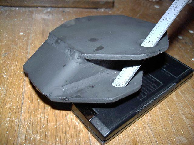
- 5. How is the lift height measured?
-
Also you may notice that the motor mount spacer is not as
"tall" as the specified lift height. Why is this? It is due
to the angle at which the motor mount rests on the frame. Lift height
needs to be measured "on the diagonal" between the mounting
holes to account for the installed angle. So a 2" tall spacer (as
shown below) may only measure 1-1/4" - 1-1/2" tall but it
raises the engine the full 2" from bolt to bolt. Also, due to mfg.
tolerances, the actual lift height may vary a little, probably +/-
3/16".
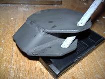
Lift Height Measurement - 6. How long does it take to fabricate and ship the spacers?
- Motor mount spacers are made to order to your specifications. Fabrication typically takes 6-8 weeks, then allow 2-3 days for US Priority Mail shipping or 6-10 days for International Priority Mail shipping. A tracking number will be e-mailed when the spacers ship.
After 25 years in operation, it's time to close up shop and move on to other adventures. Thanks to all the loyal customers over the years that helped to make this all possible. The web site will remain live.
- 7. Will my drive shaft need to be lengthened and/or will the shaft handle the increased angle?
-
Raising one end of the drive shafts will pull them out a bit. How much
depends on how high you are raising the drive train and at what angle
the shafts currently sit at and how long they currently are. You can
use a simple
triangle calculator to see how the diagonal length will change
for a given increase in vertical height. To do this measure the
horizontal separation of the pinion and transfer case flange with a
tape measure and likewise measure the vertical separation and enter
those two numbers into the side-angle-side calculator and use 90°
as the included angle (i.e a right triangle). Then note the resulting
diagonal length (this will be your current drive shaft length, you could
compare that to an actual measurement of your shaft, flange-flange).
Then increase the vertical separation by however far you want to raise
the transfer case and re-compute the diagonal length. The increase in
this length will be the extension of your shaft due to the lift. Then
compare this added extension to how much slip yoke travel you have in
your shaft *see how much slip yoke is pulled out at full droop and then
compare that to how much slip yoke extension is required to separate
the shaft). The same calculator will tell you the angular changes as
well.
- Generally if you have adequate margins on the drive shaft length and joint travel, you should be fine with the lift, I made no changes on my '85 with a 2" lift. However, if you are the "hairy edge" of length or angle, then you may need to modify the shaft a little. A drive shaft spacer can add length if needed.
- 8. How high can I lift my drive train?
-
That is a little difficult to answer as it depends on the vehicle,
engine, transmission, any modifications that may have been done to it,
etc. In general, if you have installed a body lift of X", then you
should be safe with a motor mount spacer (or drive train) lift of
X". After all, if everything fit beneath the body prior to the
body lift, then it should still fit lifted an amount equal to the body
lift. You can of course, lift the drive train less than the body lift.
- The "rub" (pun intended) comes if you wish to raise the engine (or drive train) an amount more than the body has been lifted off the frame. In this case, it is best if you measure the amount of lift that is possible on your vehicle. This is actually fairly easy to do. Simply unbolt the motor mounts and/or the transfer case mount from the frame/cross member, and put a jack underneath the end you want to lift and raise away until you contact the body. Then, measure the vertical separation between the motor (or t-case) mounts and the frame/cross member and that is the maximum amount you can probably raise the drive train. However, you likely want to allow some room for the drive train to move around under load (after all it is attached to the frame with rubber mounts). And a final option is that you can choose to cut away the part of the body that is limiting the lift height. This is sometimes done in off-road-only vehicles, where the transmission and t-case(s) are shoved up between the seats with most of the "tunnel" cut away. This is probably not too practical in a vehicle driven on the street, due to the noise, heat and fumes coming up inside the cab.
- But, the bottom line is that if you are planning to lift your drive train an amount greater than any installed body lift height, it is highly recommended that you measure how far you can raise the drive train before hitting the body. Some folks take a trial and error approach to this, ordering first one height then another height spacer and this ends up costing them more time and money in the long run, then a quick measurement prior to ordering.
- The "rub" (pun intended) comes if you wish to raise the engine (or drive train) an amount more than the body has been lifted off the frame. In this case, it is best if you measure the amount of lift that is possible on your vehicle. This is actually fairly easy to do. Simply unbolt the motor mounts and/or the transfer case mount from the frame/cross member, and put a jack underneath the end you want to lift and raise away until you contact the body. Then, measure the vertical separation between the motor (or t-case) mounts and the frame/cross member and that is the maximum amount you can probably raise the drive train. However, you likely want to allow some room for the drive train to move around under load (after all it is attached to the frame with rubber mounts). And a final option is that you can choose to cut away the part of the body that is limiting the lift height. This is sometimes done in off-road-only vehicles, where the transmission and t-case(s) are shoved up between the seats with most of the "tunnel" cut away. This is probably not too practical in a vehicle driven on the street, due to the noise, heat and fumes coming up inside the cab.
- 9. Are there any considerations when installing these spacers along with a body lift?
- Not many, you would of course want to install the body lift first in order to give you the room to raise the engine (and drive train) into. Then of course, you will need fewer components from a typical body lift kit. For example, the radiator drop brackets would likely not be needed as you'll be raising the radiator (with the body) and the radiator fan (with the engine). Also, if raising the transmission/t-case as well, you'll not need to deal with shifter issues since the shifter height below the floor will not be affected, depending on the body and drive train lift heights.
- 10. Which version should I order?
- Since these spacers are designed to raise the mounting point on the frame for the motor mounts to bolt to, you should be sure to order the version to match the engine that originally came in the frame you are attaching the spacers to. So if your vehicle originally had a 20R/22R/22RE/22RET engine, then you should order the 22R version of the spacer, no matter what engine you are planning to install in the vehicle. Likewise, if your vehicle originally had a V6 engine (3.0l or 3.4l) or later model 4-cylinder (2.7l) engine, then you need the "V6" spacers. The reason being is that the 22R style motor mount brackets on the frame are at a 55 degree angle, while the "V6" style brackets are at 48 degrees. So you need the spacer that matches the angle of the frame brackets so that the motor mount attachment points are raised vertically by the desired amount. If you were to put 48 degree spacers onto a 55 degree frame bracket, the bolt holes in the top of the spacer would be tipped inward by the difference in angle between the spacer and the frame and that would move the mounting holes inward (or outward) and they would no longer line up with the mounts on the motor.
Ordering:
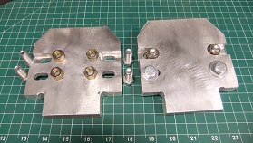
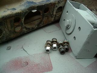
1.5" or shorter spacer 2" or taller spacers -
Price is US$129.00 for a pair of spacers and mounting
hardware (pictured above)
- Note, re-use of existing motor mount hardware to attach the motor mounts to the 2" or taller spacers
-
Ships in USPS Padded Flat Rate Envelope (US), Medium Flat Rate Box (outside the US), ~4.5 lbs.
- Tracking number and link to installation notes furnished upon shipment
- Please be sure to double check your shipping address prior to submitting the order.
- Contact 4Crawler Offroad to discuss your specific application or to place an order
- On the 1" and 1.5" spacers, we now use a new design that has slotted holes allowing for a small amount of fore-aft adjustment and also should allow for 20R-22R swaps. That is the lower holes should fit the narrower 20R frame bracket spacing and the upper holes should fit the wider 22R spacing.
US Delivery Canada Delivery Int'l Delivery
Application Notes:
- The 22R spacer is angled at 55 degrees and should fit most 22R/22RE/22RET engines. Bolt hole spacing is 95mm (~3-3/4"), some early 20R/22R motor mounts may have a narrower bolt pattern with approx. 90mm (~3-1/2") center-center spacing. If in doubt, measure before ordering. and select the "20R" style spacer in the above order form.
- The above V6 spacer should fit the 3.0 and 3.4L V6 motor mounts as well as the 2.7L 4-cyl and most of the Toyota diesel engine motor mounts, which all have a 48 degree angle and the 95mm (~3-3/4") bolt hole spacing.
The spacers are designed for easy installation with simple hand tools. A floor jack or factory bottle jack is needed to raise the engine up to install the spacers. A block of wood under the oil pan makes a convenient lifting point. You should loosen the transfer case mount and even raise it with a spacer block to assist in getting the new mounts to align properly. Loosely install the bolts and get everything lined up (no strain on the motor mounts) before tightening any of the fasteners. I found on my truck that I had to use a come-along to pull the engine forward about an inch to get the mounts to line up. This may have been the result of a bent transfer case cross member.
On spacers less than 2" tall, it is necessary to insert the bolts from the outside and place the retaining nuts inside the spacer. We now use separate hex nuts that fit into slots behind the spacer, so you'll need to get the lower bolts fit through the frame backets and started into the nuts in the slots. Then you can insert the upper nuts into the slots and get the bolts started through the motor mount and into those nuts. With all the bolts loose, you should have some adjustment room up-down (with the slotted holes in the motor mount itself) as well as some fore-aft adjustment with the slotted holes in the spacers.
Once all the bolts are in and you have the motor mounts all sitting in place, you can then proceed to tighten down all the fasteners.
- Here's how I installed 2" motor mount spacers on my 4Runner
- Here's Tim Stucky's Drivetrain Lift article on Outdoorwire.com
Of course, if you lift the engine, you should also lift the transmission/transfer case an equal amount. One method of doing this is to fabricate a custom transfer case cross member to lift the back end of the drive train. Another option, and the one I used, is the Front Range Offroad Fabrication cross member and skid plate, very nice, easy to install and you can set it for any height you want and for IFS trucks BudBuilt has some nice crossmembers in a variety of lift heights:
Note: This is just one of many steps in a drive train lift. They are all fairly easy, given the right tools and skill level, but some of the steps you may run into will remain hidden until you run into a problem. I've tried to document all the things I ran into in my lift, and had read Drew Persson's write-up and other write-ups on gas tank lifts, etc. But I still ran into other issues above and beyond what others had written about.
If you've read this far, you may be asking what would all this do for my truck? After all, 2" isn't that much (You could go up 3" like Drew did, but I went 2" for clearance reasons). Take a look at the photos below, a stock 4Runner above and a 2" lift plus new cross member below:

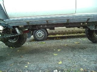
For reference, the rock sliders are 2" square tubing. The gas tank skid plate is approx. 1" below the frame, skid plate on the transfer case is perhaps 2" below the frame. The above photo is taken parallel with the frame rails, no tricky angles were used. Click on the images above to download a larger version.
Motor Mount Spacer Installation:
In order to install the motor mount spacers, a body lift equal to or taller than the spacer height must already be in place. In addition, some method of raising the transmission end of the drive train should be available. So on with the install...
-
Disconnect the battery to avoid any accidental short circuits. Check
the length of the frame-block ground straps.
- Temporarily disconnect any that may be too short.
- Temporarily remove the fan shroud and/or radiator if any clearance issues exist.
- Loosen the transmission/transfer case mount bolts and if possible raise the transmission an amount roughly equal to the motor mount spacer. For example, with a 2" spacer, a few scraps of 2x4 laid on their side makes a reasonable spacer for the transmission.
- Temporarily remove the bolts at either end of the catalytic converter to allow the exhaust to move freely.
- Unbolt the pair of bolts on each motor mount that attach it to the frame brackets.
- Place a block of wood under the oil pan and raise the engine with a floor or bottle jack.
-
Once there is adequate clearance between the motor mounts and frame
bracket, install the spacers, using the new bolts on the top and the
existing bolts on the bottom.
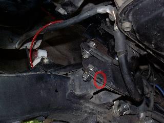
- Note that it may be necessary to modify the locating tabs on the frame brackets (see tab inside red circle in this image). If the tabs prevent the spacer from sitting low enough in the frame bracket, either bend the tabs back a little or grind a notch in the spacer base to allow the bolt holes to line up.
-
Leave all the bolts loose until you can get them all inserted.
- Bolt holes in the 2" and taller spacers are intentional made oversize to allow room for adjustment at this point.
-
If the motor mount holes fail to line up, it may be necessary to tilt
the engine to one side or the other or even move it forward and
backward as needed. Because of the angles involved, the direction to
move the engine may not be obvious.
- When I installed my spacers, I found the engine was about 1" too far back and I used a come-a-long to winch it forward, a pry bar off the firewall would also work. Once it was in the proper location, all 8 mounting bolt holes lined up and the bolts slipped right in.
- Once everything is in place, lower the engine onto the mounts, torque down all the bolts to factory specs (approx 25 ft.lbs).
- Re-install the radiator and/or fan shroud, check all ground straps and replace/relocate any that were disconnected.
- Re-connect the exhaust, making any pipe or hanger bends as needed.
- Finish the drive train lift on the transmission end and you are ready to go.
Transfer Case Spacer:
So the FROFab cross member is a great thing if you have a solid axle truck, either stock or converted, or have IFS and dual transfer cases. If your rig doesn't meet the above criteria, you'll be unable to install this cross member due to interference with the front torsion bar brackets. However, the BudBuilt cross member does address all these issues and can be ordered with a built-in lift; highly recommended.
Perhaps you are planning to do one of the modifications above but want to get started early, or you want to use one of the other low-profile cross member designs, and simply lift the transfer case up above that, or you are using the FROFab cross member and want a spacer to use to let you install and remove the cross member for servicing the transmission, etc. Realize that this spacer *will not* provide any increased under-truck ground clearance as the log hanging stock cross member will still be in it's original position.
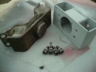
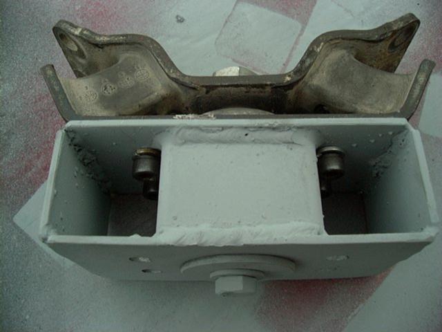
Pictured below is a 2" / 4-cylinder ('84-'95) transfer case mount spacer, 3" is also available, as is a V6 ('88-'95) t-case spacer version (80mm x 57mm bolt hole pattern w/ offset center hole). Other spacer designs may be possible, but will need the bolt hole pattern and location/size of the large hole. As with the motor mount spacers, can also do 1" spacers in a billet aluminum:
Tranny Mount Installation:
As you can see, installation is fairly straight forward;
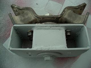
- Support the transmission on blocks and remove the stock cross member and transfer case mount
- Bolt the spacer to the transfer case mount using the supplied Grade 12.9 allen head bolts and lock washers
- Bolt the spacer to the cross member (stock unit pictured) with the supplied Grade 12.9 allen head bolts, washers and aero-lock nuts
- Bolt the transfer case mount and cross member back in place.
Transfer case spacers are no longer available, see the other options in the next section...
US Delivery Canada Delivery Int'l Delivery One item to note, if you will *not* be raising your horse collar cross member, you'll need to carefully check the rear drive shaft clearance where is passes under the cross member. You'll want to ensure you have enough clearance for the drive shaft after the lift. Different wheel bases and drive shaft configurations can affect the clearance.
Other Transfer Case Lift Options:
Front Range Offroad Fabrication has a weld-on cross member and skid plate combination:
As an alternative, the BudBuilt transfer case cross members are both functional and affordable. You can find out more about them from Bud's page:
[back to the top] Questions? -->
  <-- Comments?
email: sales@4Crawler.com
<-- Comments?
email: sales@4Crawler.com
[Last updated: 28.May.2024 ]
Visitor # 93557 since 13.AUG.2001


