Toyota Axle Tech
Contents:
[Return to my Cheap Tricks page]Introduction:
Toyota 4WD trucks up through 1985 (in the US) featured 8" axles front and rear, 8" rear axles continued at least through the '95 pickup and 4Runner.
[Return to the top of this page]Reinforced and Lengthened Spring Perches:
The Toyota mini-truck solid front axle is designed with the differential offset to the right hand side of the vehicle. This allows the front driveshaft to pass beside the engine and transmission. One of the consequences of this is that the right hand side spring perch sits up on the side of the differential housing. In order to clear the steering arm on the left side, Toyota chose to place the left hand side spring perch closer to the axle tube, resulting in approx. a 3/8" height difference between the two sides. To compensate for the height difference, the stock front springs are asymmetrical, with the right side having less arch than the left side, On top of that, since the right side is flatter, this means it is inherently "softer" than the more arched left side, so the individual spring leaves are a made a bit thicker to compensate for the loss of stiffness due the the flatter spring.
Many aftermarket front springs also offer this different arch, but many do not make the right hand spring stiffer. This results in a front end lean. Since the spring perches are located approximately halfway out on the axle, a small difference at the spring is magnified by at least a factor of two at the wheel. However, with the stock steering and spring setup, there's not a lot that can be done about this. However, if the steering is modified to eliminate the interference problems of the stock steering arm, then there is a simple fix.
Another problem on Toyota trucks that see a lot of off-road use is that the stock spring perches can become distorted from the forces of rockcrawling. The stock spring perches are a bit weak, and adding a bit of support to them before they are damaged will prevent it from happening.
A last problem with the stock spring perches is that they are only about 4-3/4" long. With the spring over axle configuration, this short perch can contribute to axle wrap. A longer spring perch can help spread the axle torque load over a longer length of the leaf spring, lessening axle wrap. Too long a perch and you can lessen the flexibility of the spring.
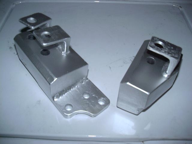
So, there are a couple of issues with the stock Toyota spring perches that can all be fixed at one time. To add some strength to the left hand perch, I cut two pieces of 1/4" wall 2-1/2" square tube and trimmed them to match the profile of the existing perch support. These pieces were then welded to the axle and perch, extending the length of the perch. Then I cut a length of 3/8" ax 2" flat bar approx. 5-1/2" long. In the center, I drilled a 5/8" dia. hole to accommodate the head of the center bolt on the spring and used a spare center bolt to align the spacer to the perch and welded the spacer in place.
It wouldn't do to have a nice beefy left hand perch and keep the stock right hand perch, now would it? I cut two pieces of 3/8" x 2" flat bar long enough to span the gap between the top and bottom perches, and then welded them in place. To fill the gaps, I fashioned pieces of 3/16" flat bar and welded those in place as well. This boxed the whole perch and also extended it 3/4" in length. All in all this project took me about half a day to finish and cost about $10 in materials.
[Return to the top of this page]Clearanced Differential Housing:
One potential weakness of the Toyota axles in extreme off-road use is the drain plug located o the bottom of the axle housing. The plug is required to drain the gear oil from the axle since there is no access plate due to the 3rd member (dropout) design. The drain plug is a low profile 24mm hex head bolt surrounded by a welded-on ring that affords some protection that is suitable for mild off-road use. However, in heavy use, the ring can get worn away or damaged from scraping over rocks, the bolt head can get damaged to the point it is not possible to get a socket on it to remove it, or worse yet, it can be knocked loose by rock contact.
In light of these problems, one common fix is to weld the drain plug in place. This prevents it from loosening up, but also makes draining gear oil difficult. A simple fix for draining gear oil is to weld the nuts onto the two lower 3rd member mounting studs (converting them into bolts) and then simply remove those two studs to drain the gear oil. This does leave a few ounces of gear oil in the housing but should suffice for routine maintenance.
While the above fix does indeed cure the problem of losing a drain plug on the trail, there is another problem. That is that the plug itself and the protecting ring hang down below the axle and their sharp edges can cause the axle to hang up instead of sliding over rocks. I suppose in time, that excess metal would wear away, but how about giving it a helping hand :-) After running welded plugs (front and rear) for a year, and getting hung up on the differential housings one too many time, I finally decided to do something about this.
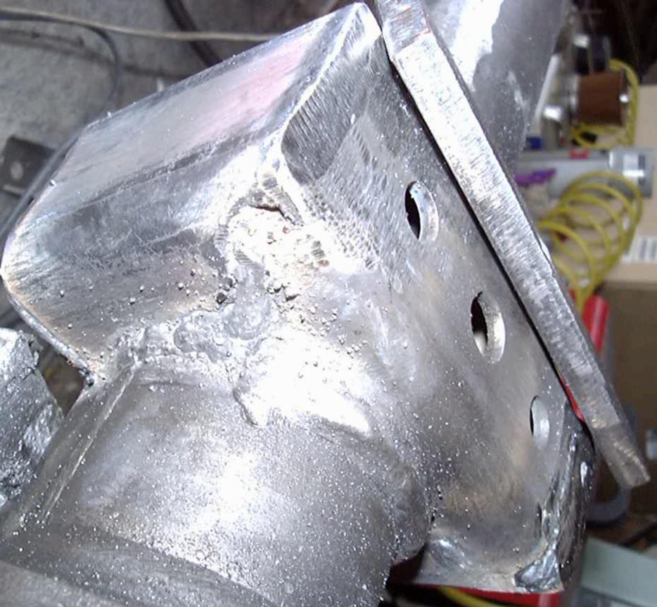
So, first step was to mark out an area of the existing housing to be removed. I settled on 3" to each side of center, which put the cut just beyond the drain plug but before some inner bracing inside the axle housing itself. I used a plasma cutter to make the rough opening, then a grinder to smooth and square up the edges. I removed the lower two studs while working on the axle and also kept some water in the housing to catch debris and soak up the heat. An abrasive cutoff wheel would also work for this step of the process.
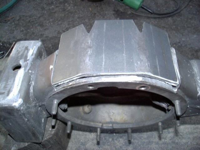
Next, I cut a length of 1/4" x 4" hot rolled flat bar 7-1/4" long, then put a pair of 30° bends in it, 1.5" from the center. This allowed the plate to conform to the curvature of the housing. Then, the opening in the housing was slowly ground out to accommodate the plate, which is designed to sit flush to the back side of the 3rd member mounting flange. Since it projects over the back side of the housing, that part was trimmed 1/4" below the mounting flange and matching angles for the plate were formed. With the plate flush to the flange, the two lower stud holes are left clear for use in draining gear oil.
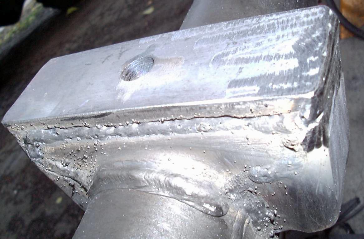
Here, you can see how the plate fits on the back side of the housing. Take you time to slowly enlarge the opening and constantly check the fit and grind down any obstructions until the plate fits down snugly inside the opening. I spent about an hour fitting the plate into the opening. Once in place, I beveled the edges in preparation for welding. I used 1/8" 7018 low hydrogen welding rod with DCEP at about 130A and slowly worked my way around the plate, making short beads on alternate sides. I kept water in the housing and also used wet rags on either side to soak up heat.
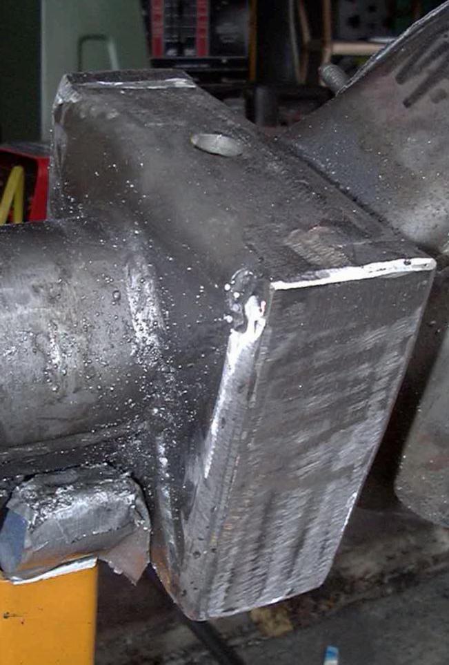
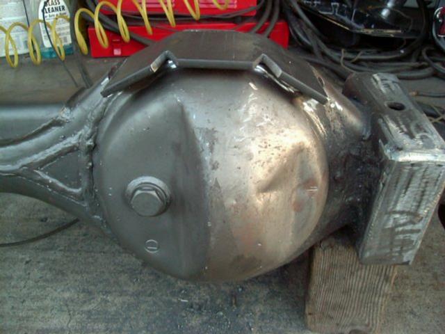
Once the plate was welded around the edges, I grooved the top side of the 3 projecting pieces of the plate, hammered them down over the bottom edge of the housing and filled in around them with weld bead. Then I fashioned another piece of 1/4" x 4" flat bar about 3" wide, with two slight bends to conform to the front of the housing and welded it in place, trimming the excess to add a reinforcing plate to the front of the housing. The stock axle housing is about 6mm thick (~1/4") combined with the additional 1/4" plate gives a 1/2" thick piece of steel up front to fend off rocks. The clearanced bottom of the axle sits nearly 1" higher than the lowest points of the stock axle (this is almost like going up 2" in tire diameter without needing any lift or gearing changes), but more importantly, the bottom of the housing is smooth as a baby's bottom so to speak. There are no sharp edges to catch on rocks, no drain plugs to get knocked out, just a nice clean and smooth underside. For protection, I wire-brushed the bare steel, cleaned it with an acid etch and zinc phosphate rust converter then top coated it with POR-15 primer followed by Chassis Black.
[Return to the top of this page]HySteer Conversion:
The normal Toyota steering setup places the tie rod below the front springs. This is fine until you get into large rocks and then the flimsy tie rod is vulnerable to damage.
Even my hybrid Toyota/Dana60 axle kept this same arrangement. Even though the tie rod is higher than stock, it still showed scars of close encounters with rocks even after a fairly easy run up the Clawhammer trail in Johnson Valley. So, something had to be done about that...
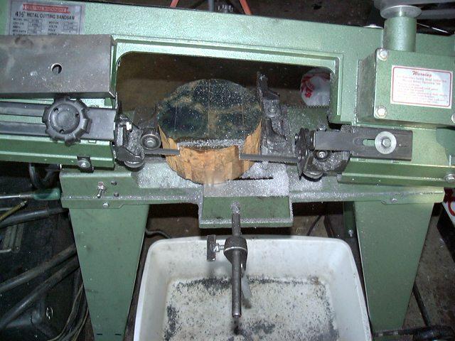

First I found a scrap of steel, 3" thick and about 8" dia. at the local steel yard. Cost $7.80 plus tax, bargain of the century! First step was to whittle 28 lbs. of steel into some useable blocks. I trimmed the ends of the block to 6" long then 4" wide...

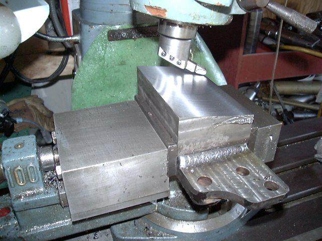
Finally, the block was sliced in two making a pair of 2" x 3" x 6" blocks, about 78 square inches of steel cut on my 4x6 bandsaw in about 2 hours! Next step was to bevel the top surface to 9-10 degrees to match the kingpin angle on the steering arms. I used a homemade flycutter with carbide bit with the milling machine head tipped to the needed angle. After milling the blocks were welded to the steering arms.
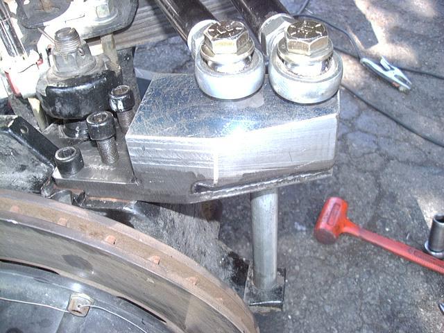
Next, 5/8" holes were bored for the draglink and tie rod ends to bolt into. These holes were drilled perpendicular to the beveled surface. This was done to ensure the rod ends would be operating at minimal angles for better strength. I retained the existing tie rod bolt with a solid spacer to add strength along with 3 allen bolts on top.
Also, I took this occasion to improve my steering performance. As designed (to keep the tie rod from hitting the differential housing), the steering arms placed the draglink end farther away from the kingpin than the pitman arm length. This resulted in less than lock to lock steering and a greater turning radius. I moved the drag link in about 1/2" less than the pitman length to ensure lock to lock steering even at full droop. I then moved the tie rod in closer to the kingpin enough to clear the draglink and to get it closer to the axle housing (see the reason later on).

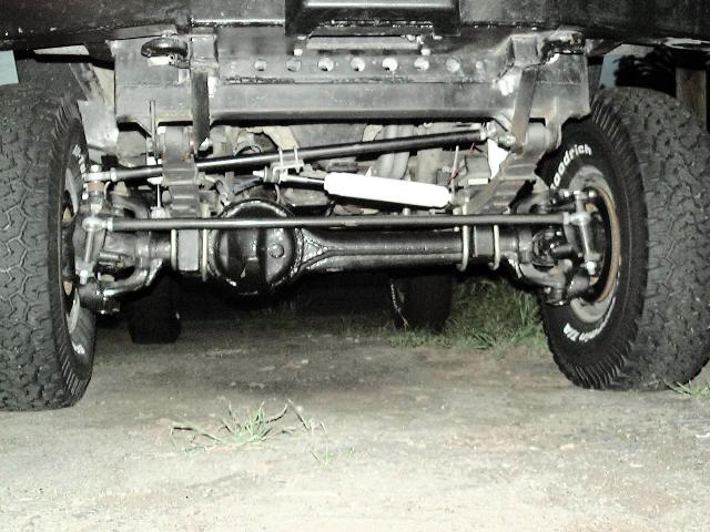
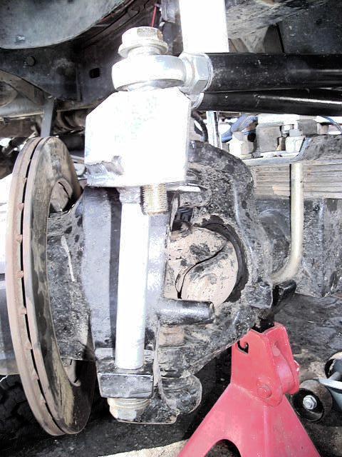
And here is the finished product. Tie rod is tucked up above the springs with the draglink, safely out of harms way.
After fitting everything up, I added top brackets for each rod end, placing them in double shear for added safety. I then used a high temperature ceramic paint and baked it on in an oven for a good durable finish.
Cost for the project was $8 for the steel, a pair of bandsaw blades @$18/ea. (I was using a 0.035" thick blade and that was too much for my little saw, I now run 0.020" blades and they work much better) a bit of cutting oil, some paint, oh and $1700 for the milling machine (I think I'll be able to use that on some other project) and 2 days in the garage and driveway!
[Return to the top of this page]Hydraulic Assist Steering:
So, besides raising my tie rod out of the rocks, my other reason for going to HySteer, was to get the tie rod up closer to the top of the axle housing. Why you ask? Well, it makes it a lot easier to connect things to the tie rod, you know like steering stabilizers or hydraulic rams, that sort of thing...
I went with a hydraulic assist steering setup from All Pro Offroad. The kit utilizes parts from Howe Racing Equipment including a new high volume power steering pump, modified Toyota IFS steering box and of course the hydraulic ram itself. The basic idea of the system is quite simple; two new ports are added to the steering box to feed hydraulic fluid under pressure from one port to the hydraulic ram and allow fluid to return from the other side of the ram to the steering box. The steering box continues to function normally, providing approx. 60% of the steering force. The ram applies the rest. So, on with the upgrade...
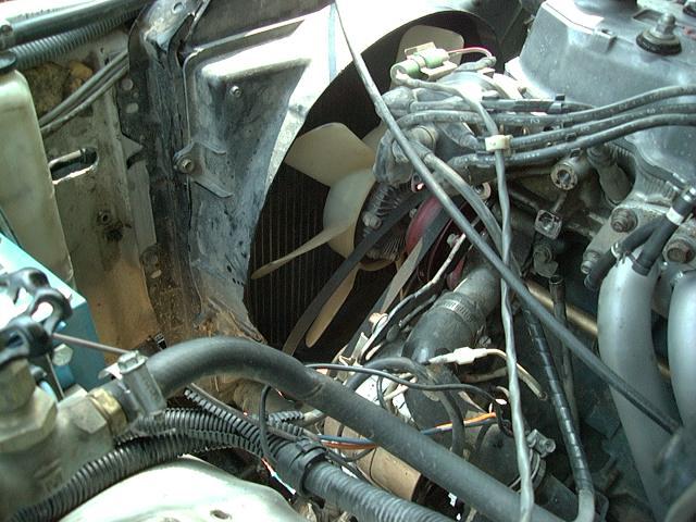
First step is to remove almost all the stock power steering components. The only stock part re-used is the idler/tensioner pulley and bracket and the v-belt. I removed the pump, its bracket, the reservoir, the high and low pressure lines and the old steering box.
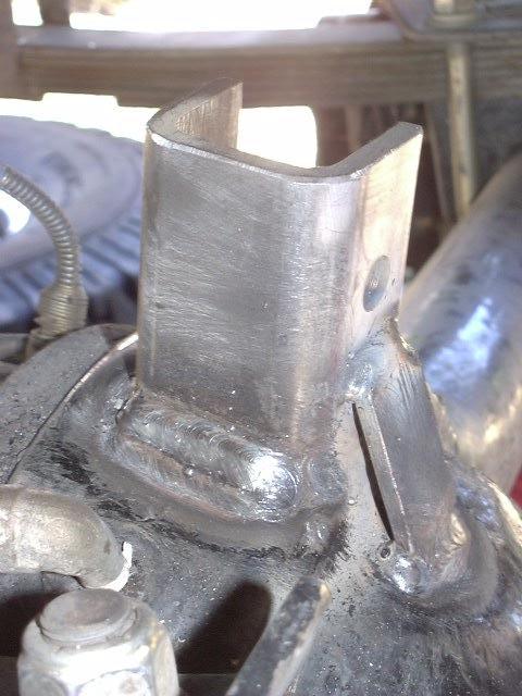
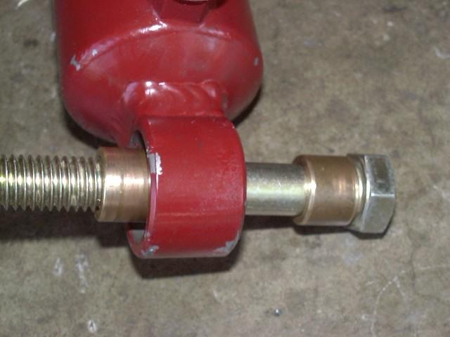
Next, I fashioned a mounting bracket out of some 2x2x1/4" square tubing. This was cut to a "U" shape, drilled for the ram end bolt and finally welded to the top of the axle housing. I used 3 passes of 7018 welding rod at about 140 amps to get good penetration and build up a good fillet weld. I added a front brace for added support. Next, I turned some brass bushings to fill in the 1.5" ID of the bracket. Shown is my initial bushing, 1/2" on each side, but later I made the front bushing 1/4" and the rear 3/4" to keep the ram closer to the tie rod to minimize the angle. This is the main reason for the tie rod relocation I did in the HySteer conversion, above.

Next, time to start installing the new power steering parts. A new Howe pump is installed in a new bracket. I installed the new steering box using the existing bolts and mounting holes. I found the new valve on the steering box is longer than on the old box. This pushed the splines on my steering shaft way up, luckily the 3" body lift I had had pulled the shaft out a bit, so it ended up just barely fitting.
Alignment:
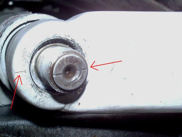
When re-installing the pitman arm, be sure to line up the scribed lines on the arm and sector shaft (see image below-left). Then turn the steering wheel to straight ahead and install the steering shaft.

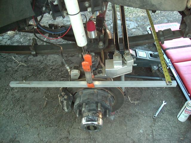
After connecting all the parts, its fairly easy to align the steering. I clamped two straight edges on each brake disc, the adjust the wheels for toe in by measuring across the front and rear, I used about 1/8" toe across the 3' bars.
- Why 3 foot long bars?
-
Well, that is about the diameter of the tires, 3' = 36".
- Also, I happened to have a 3' long level that I used for one side (photo above-center).
- On the other side was a longer piece of angle, I simply marked it 18" on either side of center and used those marks, you'll note in the above-right image, the tape measure is not at the end of the bar, rather in a few inches.
- Also, I happened to have a 3' long level that I used for one side (photo above-center).
- Why 1/8" toe-in?
-
Factory spec is 1mm +/-
2mm which equates to -1mm to +3mm, 3mm = 1/8" and with a
larger diameter tire, 1/8" is reasonable.
- Also, using a typical tape measure marked every 1/16", the 1/8" difference is fairly easy to see
- Since this initial setting, I now run with toe-in between 1/16" and 0"
- Also, using a typical tape measure marked every 1/16", the 1/8" difference is fairly easy to see
- No 3' long straight bars to use?
-
Simply measure the toe-in off the tire tread.
- Pick a place on each tire to measure from that offer good sharp edges.
- To be really accurate, mark the measuring spot when it is in the front, then roll the vehicle forward or back 1/2 tire rotation until the marks are in the back and measure the same two points.
- I usually just use the tire tread to check and correct my alignment.
- Pick a place on each tire to measure from that offer good sharp edges.
You can also sight down the bars (or tires) to set the draglink to straight ahead and centered by lining up the tread on the rear tires equally down each side. You can get remarkable good readings this way. Afterall, figure you have approx. 8' between the front and rear tires. At that distance, a 1" difference in where the left and right tires line up with the rear tires is equal to an error of 0.6 degrees. You can easily eyeball the alignment to 1/8"and that puts you within 1 minute of arc. Who needs a $10,000 computerized alignment rack when you can do as good with your eyeballs and a tape measure.
Important note: You should re-check the toe in with the tires on the ground after doing the above. Easy enough to do you putting a mark around the circumference of the front tires and then measuring the front and rear width off that mark. Sometimes the weight of the vehicle will deflect the wheels inward at the top and that ca slightly affect the toe. Also helps to roll the vehicle back and forth a little to get things into the normal orientation and release any stress from jacking the front end up and down. If you do notice a change in the toe measurement, make a note of the amount of change and then you can take that into account next time. For example if you set 1/8" toe in in the air then measure 1/8" toe out on the ground, you know your front end changes 1/4" with weight on it. So next time you need to align it, set it to 1/8" + 1/4" (or 3/8) toe in. Then with weight on it, the tires should push out the 1/4" and you'll end up at approx. 1/8" toe in.
By putting all parts at their centers, I found my steering wheel was level, I got rid of the steering pull I used to have, vehicle tracked dead straight ahead, and I even had a bit of return to center despite the hydraulic assist ram :)
Now, what about camber and caster you might ask?
Well, camber is pretty much set by the axle housing. The two knuckle (or trunion) bearings, drop into recesses in the steering knuckles and that sets the camber. There are purportedy eccentric knuckle bearings available in Australia that allow a small amount of camber adjustment by having the center hole in the knuckle bearing offset a bit from center. As imagined, you would not be able to get more than a degree or so of correction from something like that.
For caster, that is fixed by the relationship of the spring perches welded to the axle housing and the relationship of the leaf springs to the frame (assuming the steering knuckles have not been rotated). So caster can be changed by either modifying the perches on the housing or by adding a steel shim or wedge between the springs and axle/perch. You can find more about that and also how to get a rough measure of caster on this web page.
On my 4Runner, I've tried to keep the caster angle close to the factory specs. Over the years, I installed a dropped front spring hanger, that lowered the front spring eye by 2.5". To offset that, I installed 3.5" longer than stock spring shackles. As a result, the rear end of the springs is approx. 1" lower than the front end. This results in about 1 degree more positive caster angle than stock, which was around 2 degrees. For a while I ran the caster 0.5 - 1 degree less than stock and had bad "death wobble" at around 35mph. Going to 1 degree more than stock eliminated that problem. My thinking is that the more caster angle added, the worse the pinion angle gets. So, run the least amount of caster that results in stable steering and call it good.
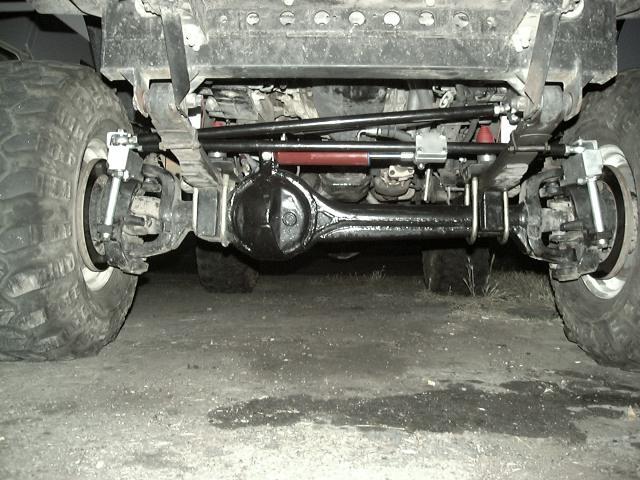
Here's the finished product. Steering parts tucked up safe from trail obstacles. Ram is in-line with the tie rod and works marvelous on and off-road. Even with aired down 15" wide tires at a dead stop, its easy to palm the wheel from lock to lock. On the road, it takes a bit to get used to the *very* light steering touch. Steering is precise, absolutely no backlash, there is a tiny bit of road feel. Its very light but once you get used to it, it feels normal.
On a recent 3-day trip across the Dusy/Ershim trail the ease of steering was very nice, lots of tight turns between trees and around rocks. After 6 hours on the trail, there is no fatigue, this is real power steering!
[Return to the top of this page]Rear Axle:
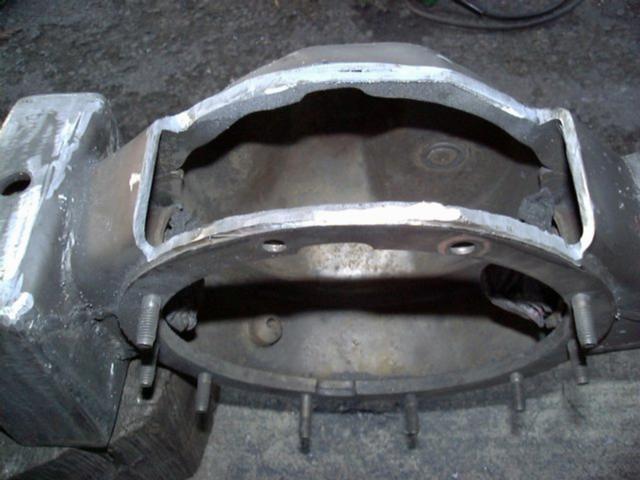
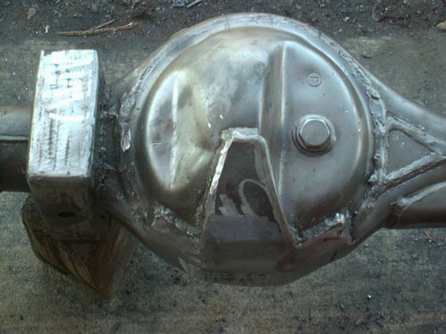
After a year of running a clearanced front axle (and stock rear axle) and finding out how much of a difference it made (read: front easliy clears trail obstacles only to get hung up on the rear axle), it was time to do the rear axle. I had been planning some other rear axle upgrades including swapping my narrow '85 rear axle for the wider IFS-style rear axle. After stripping down the housing, it was shaved of the drain plug and lower part of the housing. A 1/4" steel plate was welded in place and ground smooth:
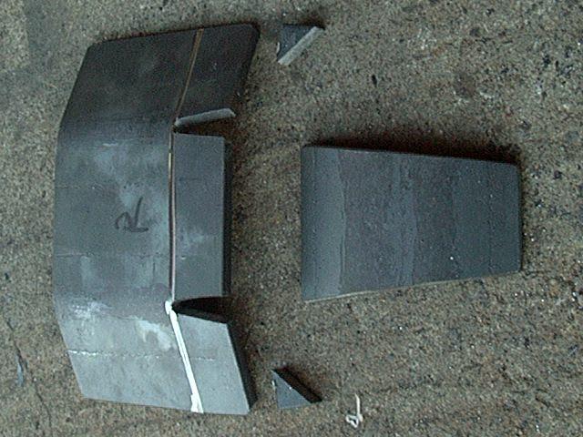
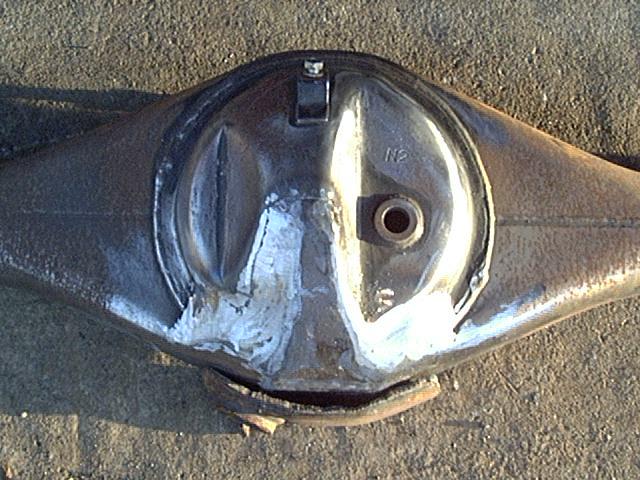
You can see in the image on the right the bottom part of the axle that was removed and the smooth piece that replaces it. On the rear axle the ground clearance is only increased about 3/4", but the more important benefit is the reduction in drag, there is nothing to get hung up on rocks.
[Return to the top of this page]Disk Brake and Full Floating Axle Conversion:
As part of the rear axle upgrade, I decided to go with a full floating rear axle. A full floating axle is stronger as the axle shaft only transmits torque and the axle housing (and spindle) carry all the load. After years of fighting with bent axle shafts and inadequate wheel bearings, this was an important point for me. Also, the Front Range Offroad Fabrication full floater kit I chose to use, had disc brakes, which would be a big improvement in braking over my small drum brakes. The kit was very well thought out as it also included an adjustable proportioning valve to replace the troublesome stock Load Sensing Proportioning Valve (LSPV) as well as using disc brakes with integral mechanical parking brakes.
 |
 |
| A: Rear F/F axle | B: Disc brake detail |
 |
 |
| C: LSPV valve elimination | D: Rear locking hubs |
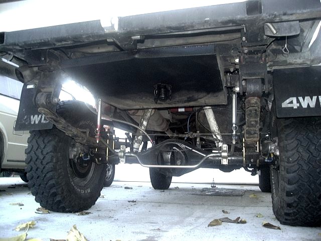
So at long last, got the axle built and installed in the summer of 2009.
In picture A, above, you can see the overall rear setup. The 3" wider IFS rear axle housing is shaved and plated with a high clearance axle kit. Pictured also are the original Rancho 9012 shocks, those have since been changed to longer remote reservoir Ranchos. Still working on getting those shocks dialed in and positioned.
In picture B, you can see the detail of the Supra rear disc brakes and brake line plumbing. I ran the hard lines under the springs and behind the u-bolts and fashioned a bolt-on plate to protect them from trail damage. Then Earls brake like fittings were added to transition from the hard line up to a length of s/s flex line used in place of the rubber line supplied in the Front Range.kit. Since the Supra calipers are essentially mounted upside down on the F/F axle, you need to unbolt them and roll them to the front of the axle to bleed. I did not like the way the supplied rubber hose handled that, so went to a slightly longer s/s flex line.
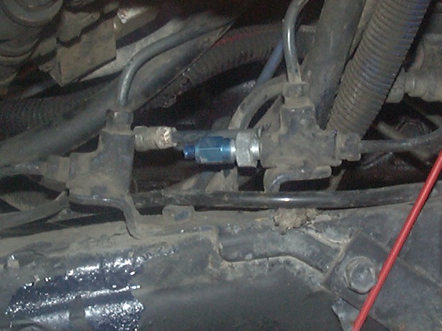
In picture C, you can see the the block off plug I added up front to eliminate the stock LSPV valve, which is no longer used. In back, where the LSPV used to be, the line from the brake m/s up front connects to the brake line to the axle. Then the line that used to run from the LSPV to the front brake circuit (for the Bypass function of the LSPV) is plugged. For folks wanting to do a similar LSPV elimination and/or disc brake line install, all parts are available from 4Crawler Offroad.
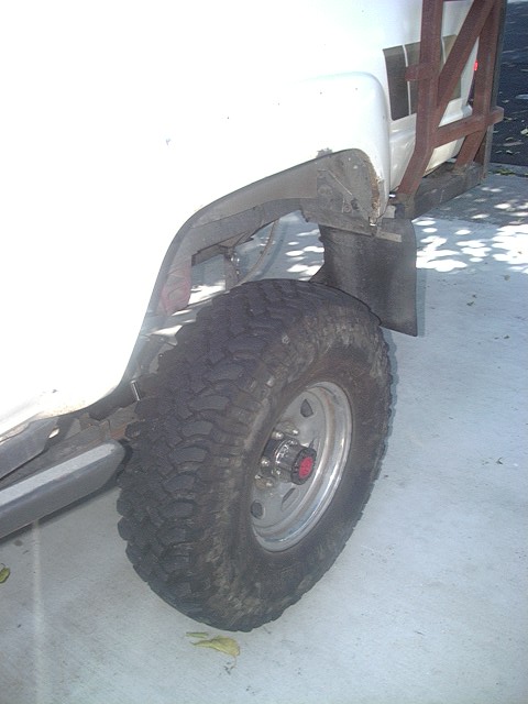
And finally, in picture D, you can see the end result, locking hubs on the rear axle. I originally installed some FJ-80 drive flanges and do carry those as spares. But, to beef up the stock Aisin hubs, I installed a set of Longfield cro-moly hub gears and also a set of ARP hub studs. Should make the rear axle pretty stout with that and the cro-moly axle shafts in the full floating setup. And yes, the rear hubs do work. Lock up the front hubs, unlock the rear hubs and slap it in 4H and you have instant FWD. Kind of different driving now in FWD that I was used to with the stock front axle. With the stock front birfield/CV joints, you have a very smooth front axle drive, even while turning. Now with the u-joint D60 outers, it is VERY lumpy while turning. Feels like something is broken, badly. But once you straighten out the wheels, it is fairly smooth. And with the soft rear springs up front, you get a lot of front lift when you accelerate. When I had used FWD before with my original stiff lift springs, I found it was a lot better behaved compared to now. But the idea was not to have a FWD truck, rather one that is more reliable off-road.
And so far the driving results on and off road have been great. The biggest change is that it drives smooth on pavement. I had been fighting bent rear axle shafts for many, MANY years on my old '85 axle. I think I had between 6 and 8 axle shafts and all were bent to one degree or another. Was interesting watching the truck on the smog test dyno, it was hopping all over the place. Now, with the full floating axle spindles and double bearings (just like the front axle), it rolls like it is on glass. And off road, it just works like normal, except now the axle is wider, the housing is shaved for addded clearance, and it has mounts for a sway bar (with disconnects) so it just works better all around.
[Return to the top of this page]Reinforced and Lengthened Spring Perches:
Did a fairly simple addition to the spring perches to both lengthen and strengthen them. I cut some 3/8" thick steel plate the width of the spring perch and long enough to fit down to the center of the axle tube. The top edge was beveled to match the top of the spring perch. Then these plates were welded to the front and rear of the spring perches and ground smooth. I rounded the leading and trailing edges to avoid creating a stress riser on the spring pack.
This simple upgrade adds a bit over 3/4" to the length of the perch, making it 5-1/2" long. Thus helps reduce axle wrap a bit and also beefs up the thin metal of the factory spring perches.
[Return to the top of this page]Emergency Brake Cable Modifications:
Still working on a final solution for this. I plan to make use of a steel tube with through bolt into the e-brake lever on the caliper. At the top of the tube will be a heim joint though which the bolt will pass. Into the threaded end of the heim will be an adapter to allow attaching the e-brake cable. The tube will be tall enough to clear the 8 leaf spring pack and the heim joint will keep the motion free.
I tried a similar setup before, sans heim joint. But with the large swing angle of the caliper e-brake lever, the mechanism would bind up before it pulled the e-brake on fully. Thus the new design which should move in a wider angle without binding.
[Return to the top of this page][Return to my Cheap Tricks page] [Author: Roger Brown] [Initial Creation: 06.FEB.2001]
Visitor # since 19.SEP.2001
[Last updated: 11.June.2023 ]