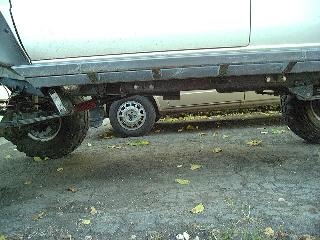
Toyota Drivetrain Lift
Contents:
[Return to my Cheap Tricks page]Introduction:
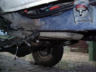
Let me start by saying this is a long and drawn out project. It started a few years earlier when I did a 1" body lift to help with tire clearance. The lift helped a bit with the tire rubbing problems, but didn't solve it. One of the "advantages" of a body lift over a suspension lift is that it has a lesser impact on the vehicles center of gravity (COG), as only the relatively light body is raised while the heavier drivetrain and frame stay put. So, anyway, I was happily running a 1" body lift, cured the tire fitment with other techniques and then I go on a run with Drew Persson and get a good look at his IFS 4Runner. Something looked odd, there is nothing visible below the frame rails, no gas tank no transfer case, and no crossmember. Turns out, he has a 3" body lift and a 3" drivetrain lift, which neatly tucks everything up between the frame rails.
While a body/drivetrain lift does impact COG to a greater degree than a body lift alone, it is not quite as bad as a full suspension lift, since the frame, springs and axles stay the same. The basic idea is to lift up all the low hanging items like the oil pan, transfer case and gas tank, and leave the rest of it alone. I'm fairly happy with my suspension as is and just want to get rid of the things that cause my truck to get hung up on the trail.
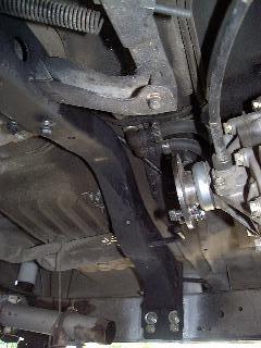
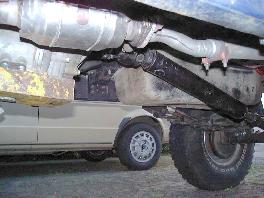
So, that started the gears turning and about a year later the plan had started to come together. It took one other event to get it going, though. A few years ago, I had a dual transfer case installed. With the 1" body lift, it fit fairly well, although I did have some trouble with the output flange of the transfer case getting somewhat close to the rear heater hoses. I did a 1" rear heater lift to relocate the hoses up higher to fix this. Anyway, the dual case setup was great off road, but on-road, my rear driveshaft was not happy. After repeated efforts to balance and align it properly, I came to the realization that a double cardan (i.e. CV) style shaft was the real solution to the vibration problems. A shaft was built, installed and vibrations were history, at least for a while. A little investigation revealed the CV head was very close to the "horsecollar" crossmember that supports the gas tank. Not only was it real close, in fact it would hit it under load as evidenced by the scrape marks on the CV and the crossmember. Not only that, but when it hit, one of the grease fittings was scraped off the CV, allowing the grease to fly out and rapidly wearing the bearing out (causing the driveshaft vibration to return).
The combination of the dual transfer case moving the output flange 6.5" back and the longer CV joint head effectively pushing it back even farther, the only option was to add some clearance up front (as well as installing low profile grease fittings in the CV after getting it rebuilt). So, it was time to start cutting...
[Return to the top of this page]Process:
Actually, there are several areas that need to be addressed in a drivetrain lift. There are three connections between the drivetrain and frame that must be modified, namely;
- 2 Motor mounts
- 1 Transfer case mount
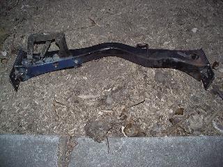
Then there is the infamous horsecollar crossmember, so called for its resemblance to the old horsecollars used to pull wagons. Then finally, there is the rear support of the gas tank which must be modified since the front of the gas tank hangs from the horsecollar.
My drivetrain lift had to take into account a number of factors. I already had a 1" body lift and had "things" set up for that. The radiator had been dropped 1", the transfer case shift levers had been raised 1" with custom short throw shift linkages and I was also wanting to increase clearance between the transfer case and rear driveshaft, so I opted for a custom 3" body lift of my own design, and a 2" drivetrain lift. This would essentially leave me at the same body-drivetrain spacing I had before and give me an extra inch or so at the rear driveshaft. Since 3" is about the maximum body lift you can safely do, that set the upper bounds of the lift. I worked my way down from there.
[Return to the top of this page]Motor Mount Spacers:
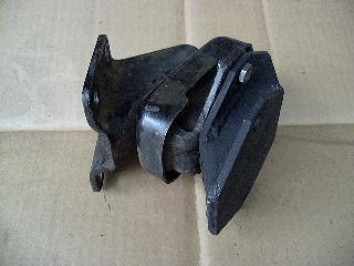
The Toyota 4-cyl. motor mounts have approx. a 4" x 4" square base plate angled at 35° to vertical and two bolts holding the mount to the frame. Luckily, I had a spare motor mount in my parts box which made the design much easier than trying to take measurements on the truck.
I cut 2 pair of plates out of 3/16" flat stock, beveled the corners and then used 2-1/2" square 1/8" wall tubing, cut on a bevel to make the spacer. The ~55° cut in my 4x6" HF bandsaw required some gymnastics and trimming of the saw to gain clearance for the square tubing to fit, but the results were excellent. Note, study up on your trig. before attempting to do this at home. Laying out the cuts and dimensions for a 2" lift take some work. If anyone is interested I can build you a set of spacers like I used. I use a spare motor mount as a template for the base plates and weld in a section of square tubing cut at the same angle, so they fit perfectly. 1.5" is about as short as this design could be used. It should be possible to make a 1" spacer out of solid stock with threaded holes for the mounting bolts. With this little lift, there would be no need to raise the "horsecollar" crossmember.
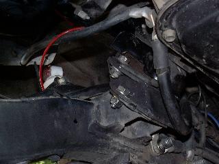
In the above left photo, you can see the factory motor mount and engine bracket bolted to the spacer. Even though I designed it and I know it is correct, it sure as heck doesn't look right to me, but on the right, you can see the photo of the spacer installed and it does indeed lift the engine up exactly 2" from stock. I still have to re-install my motor mount retaining chains, the old ones are too short. The chains attach to the bolt visible just below the ground strap in the above-right picture, and they wrap around the top of the motor mount.
Making the spacers was the easy part of this step of the project. When I went to install them, I jacked up the engine, attached the spacers and then lowered the engine and found the holes were off my nearly an inch. For some strange reason, my engine engine/transmission unit was about 1" too far back. I lifted the transfer case up to clear the mount from the crossmember, then used a come-a-long to winch the whole thing forward in the frame. Once it popped loose, all the bolt holes lined up, bolts were installed and torqued and the engine lift was done.
[Return to the top of this page]Horsecollar Crossmember:
So, the next obstacle to take care of is the horsecollar crossmember. First the gas tank must be drained and removed. In the 4Runner, you can access the fuel pump and filler hoses through the hatch under the rear seat. Remove the 6 bolts that hold the skid plate then 6 more that hold the tank and drop it down. The first time I did this job, I used a floor jack to lower the tank, but it is not very heavy and I found that laying on a creeper under the tank, I could easily lower and raise it my hand a whole lot faster.
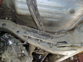
With the tank out of the way, you can see the back side of the crossmember (above left). Notice the bracket where the 4Runner gas tank installs to (the one with the bolts and welded on nuts). 2" above it is the unused bracket where the pickup gas tank would normally mount.
- Note: Since the pickup bed lacks the 2" dish the 4Runner rear seats require, its tank sits 2" higher. A common modification used by 4Runners with 2" body lifts is to just lift the gas tank by 2" using this bracket.
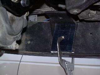
On the above-right picture, I've cut the crossmember out of the way. I used a plasma cutter to do this job, it made a nice clean cut on all 4 sides, leaving approx. 1/4" of the original crossmember attached to the frame. Since I wanted to avoid unnecessary welding on the frame, I fashioned a piece of 1/4" steel plate to fit inside the old crossmember attachment point, then welded it to the remnants of the crossmember flanges. Finally 4 mounting bolt holes were drilled and tapped into the plate and frame behind to serve as attachments for the raised crossmember.
On the crossmember, I trimmed approx. 3/16" off each end to allow for the extended mounting plates. I welded the plates to the crossmember, then added a total of three gussets (only one installed above). If you look at the middle of the horsecollar, you can probably see the bright shiny spot where my CV joint was rubbing. I had to temporarily cut off one of the catalytic convertor hangers to fit the crossmember in my horizontal bandsaw for the cut. I later re-welded it in place. I used 4 7/16" Grade 8 bolts to attach each side of the crossmember to the frame. The holes were tapped through both the 1/4" plate and the frame metal.
I had to fabricate extensions for the brake and gas line clamps to get them up and over the now 3" higher crossmember. I re-routed the emergency brake cable to fit below the gas tank and also had to re-route my 1/0 battery cables from my dual battery tray, that sits behind this crossmember, next to the gas tank...
[Return to the top of this page]Gas Tank:
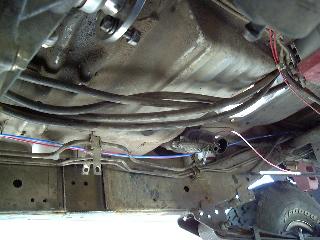
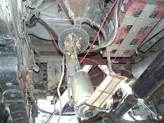
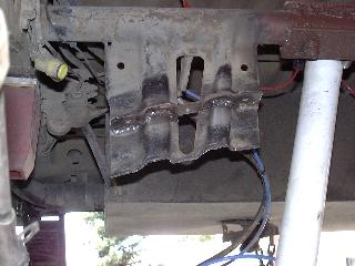
The gas tank, as mentioned before, attaches in front to the now lifted crossmember, and in back to a metal bracket attached to the round tube crossmember over the axle. You can just see the stock rear bracket behind the fuel pump in the below-left picture. Also visible is the red frame of my dual battery tray. The plasma cutter made quick work of slicing off the angled flange which was then modified slightly and welded up about 3" higher on the bracket, visible in the image to the lower right. I did have to slice off the excess metal below the mounting flange before installing the tank. Note, if only raising the tank 2" (on a 1st gen 4Runner) simply remove the 2" drop spacer from the front crossmember and use it in back to raise the mounting bracket 2". On a pickup or for more than 2" of lift, you'll need to do some more work.
After reinstalling the tank, the results are quite dramatic. Both pictures below were taken without the skid plate installed.
Notice the heavy battery cables in the above-left picture that I had to re-route around the gas tank, since the 1" gap that I had used before is now gone. Also, not as apparent in the above-right picture, is that the catalytic converter and the entire exhaust now is up inside the frame rails. This is a "free" benefit of the drivetrain lift. One point to note is that since I raised the engine (and therefore the exhaust header) 2" and I raised the horsecollar (and thus the catalytic convertor) 3", there is a bit of a mismatch in heights. Luckily, I used flex tubing in my custom exhaust installation and it accommodated the difference easily. I plan to ultimately have a hard exhaust pipe run once I'm done with all the mods. This is about the 3rd time stuff has been moved around since I installed it a year before.
NOTE: This technique will not work on the 2nd generation (1990 and later) 4Runners, at least those equipped with the stock coil spring suspension, as various suspension brackets are in the way.
- Here's a web page that describes a different type of gas tank lift for the 2nd-gen 4runner
- Here's an option for the 1st gen Tacoma pickups
Transfer Case Crossmember:
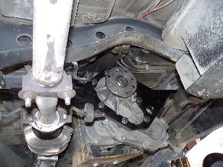
This is the last step of the project and probably the most involved step of this project. The stock Toyota crossmember is very poorly designed with respect to off-roading. It is both overly thick, decreasing ground clearance and is made out of thin sheet metal, susceptible to damage. Also, the factory supplied a flimsy piece of sheet metal to "protect" the 4WD section of the transfer case. On mine after it had been bent a few times, I removed it. With dual transfer cases, I wanted a crossmember that both supported and protected both transfer cases. I already had a spare transfer case mount and what better place to carry a spare than attached directly to the 2nd transfer case. In stock form, the cross member hangs nearly 6" below the frame rails. It is 2.4" thick and the transfer case mount itself is 3.5" below the frame.
In many respects, the drivetrain lift simplifies the design of the crossmember. Since it has less height difference to accommodate, the angles are less and with two attachment points, the strength can be increased. I started out working off a piece of steel channel to serve as the central support for my crossmember design. After fiddling with this for a while, I had some ideas but was not real happy with any of them. Also, I was not quite sure my existing transfer case location was correct either, it seemed to be offset to the passenger side too much, so I happened upon a neat crossmember design made by Front Range Off-Road in Colorado:
Looks like this product would solve my sloppy tranny mount problem, raise the crossmember and provide an effective skid plate in one ready-made package. The installation went very smoothly.
I had the transfer case raised up 2" off the stock crossmember already.
I simply bolted the new crossmember to the output section of the transfer case (using the longer bolts supplied in the kit). I drained the old gear oil prior to pulling the bolts and removed the rear driveshaft and parking brake cable for easier access. I found the crossmember just cleared my exhaust pipe which had been raised 3" (compared to the 2" higher crossmember location).
Then, I attached the rubber bushings and bracket to the ends of the crossmember and tack welded the brackets in place. Then, after removing the rubber bushings, I finished by running a bead all around the brackets, let them cool, gave them a few shots of paint and then re-assembled the bushings.
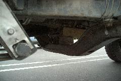
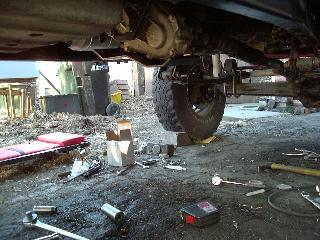
At that point, I was able to remove the stock crossmember and bolt up the skid plate to the old tranny mount holes. I did have a bit of trouble getting the holes to line up, so I ended up drilling the skid plate holes out to about 9/16" or so to get enough play to get it bolted up. Apparently, there is a fair amount of variation in hole spacing. FROF is planning to modify the design a bit to accommodate this problem. From the before and after pictures, you may be able to see I had 14.5" of clearance (tape measure case is 3.25") and after I had an even 20", or a gain of 5.5". Actually, the lowest point is now the front output section, which is about 2" below the main part of the skid plate (see below). It is 2" higher than it was before owing to my 2" drivetrain lift and more importantly, it has a nice thick chunk of steel below it for protection!
Wow, that is a slick looking underside! Gas tank skidplate is 1" below the frame, transfer case skidplate maybe 2" below. Only things that hang down are the front and rear drivelines and the axles (note to self: "Keep an eye out for some Unimog portal axles" :-)
I did get a chance to try this out off-road. I joined a small group to run the Fordyce Creek trail in the Sierra Nevada mountains of California (home of the famous Sierra Trek). Was the first time I didn't have to worry about dragging my belly. The other two rigs in the group were short wheel base Jeep CJs, so I simply followed their lines, ignoring my 20" longer wheel base. I didn't get hung up underneath, although the next day, I did see some nice deep scratches in the heavy black powder coat finish on the skid plate. I guess you can never have enough clearance underneath, but as long as you can slide over the obstacle without getting hung up, maybe that doesn't matter.
The other benefit of this setup is that it is much more rigid than the stock tranny mount. I used to get enough play in my shifter levers to whack an unsuspecting passenger in the knee. I even tried putting two stock tranny mounts on my dual transfer cases (no noticeable difference). Now, I get at most 1/4" of play and now it is more a front to back motion vs. side to side. The more rigid drivetrain seems to reduce wheel hop as well.
[Return to the top of this page]Rear axle shims
So, if you raise the drivetrain 2", do you have to worry about your drive shafts? If you run a CV rear shaft, definitely yes, I had to change my rear shims from 5° to 8° to get the bottom u-joint back into the desirable 1°-2° range. Luckily, I was able to do the measurements and make the shims myself.
[Return to the top of this page]Related Projects:
OK, so while not part of the drivetrain, but what's the point of lifting everything else only to get hung up on the front or rear bumper or your nerf bars? The whole idea of this project was to lift all the low hanging stuff up as high as possible (good for clearance, bad for COG) while leaving all the stuff that didn't need lifting alone (good for COG). So anything that hung down or stuck out was fair game.
Some folks get clearance by sticking tall and often stiff springs under their truck. While this gains clearance, it lifts everything up. I was happy with my springs, they run nearly flat and have loads of droop. But, being flat, things that hang below the frame are too low. Not wanting to change the springs, I opted to lift the things that needed it.
[Return to the top of this page]Front Bumper:
The bumper was already there, I liked it and saw no reasons not to keep it. When I originally mounted it, I tried to make use of factory mounting holes so the bumper ended up attached directly to the front frame crossmember. Excellent for strength, but cut into my approach angle somewhat. When I dropped my front spring hangers, I designed the spring hanger bracket to also support my bumper and vice versa. So, once the additional 2" of body lift was on (3" now, 1" before) I was free to lift the bumper.
It took me about a day to do this project, including the 2" spacer blocks to lift the bumper up and also provide a mounting point for my tow hooks (they used to be up on top of the bumper). The blocks are made of 2x6" - 3/16" wall steel with top and bottom plates of 3/16" flat bar, holes are sleeved with steel tubing for 1/2" grade 5 bolts. The tow hooks mount to welded in nuts and the blocks are also welded to the frame extensions that also are part of the spring hanger bracket mounts. This is made of 3/8" x 2" steel bar, bolted and welded to the frame. Luckily, there were factory bumper mounting holes 2" above the ones I used for securing the rear of the winch tray, so I re-used my old bracket in the higher holes. This bracket is 2x2 angle with two bolts into the frame and then it is captured by two of the vertical mounting bolts that go through the spacers, above. This bracket helps constrain the bumper from tilting downwards. To resist winch pulling forces, I used a pair of 3/4" grade 5 bolts that pass through sleeves in the front body mount brackets and through the spring hanger bracket and finally the bumper. This was all the support I had before, but to tie it all together even better, I added a pair of bolts that connect the rear of the bumper to the sides of the spring hanger bracket extensions that I added for this very purpose. This way the strength of the bumper adds to the spring hanger bracket and the frame, hopefully avoiding the common frame stress cracking in this area.
The new tow hook location should be stronger as well, since they are pulling straight off the centerline of the frame rather than approx. 5" higher. I now have 28" of clearance under the front bumper w/ 33's and only 26" back to the axle center, so I've broken the 45° approach angle barrier. A set of 35's will net me another inch. Overall, I'm really happy with the way this bit of the project worked out. Cost was about $10 for materials, and when added to the spring hanger bracket, I netted 4.5" (2+2.5) of front end clearance and improved my approach angle from 41° to 47°. Still not in the Tough Truck class, but better than it was.
[Return to the top of this page]Rear Bumper:
My old bumper was very heavy duty, but with the 3x5" tubing, it was too tall for my needs (5" was vertical) and the tire carrier design required the bumper be placed too far back for good departure angle. So, part of the plan was to build a new bumper after installing the 3" body lift to replace the old one.
The key design goals for the new bumper were to maximize departure angle, provide adequate rear end body protection and to support a swing out tire carrier rack. I chose to use 2-1/2" - 1/4" wall square tubing for the majority of the bumper. The small size ensures adequate clearance, it works well to allow 2" receivers to be used, and the 1/4" wall thickness should stand up to extreme abuse. To facilitate attaching to the stock rear bumper attachment points, I designed a two-piece bracket, one piece that slips into the ends of the frame then the other piece that is attached to the bumper itself that bolts up to the flange on the frame bracket.
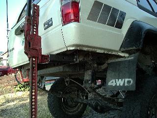
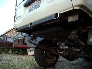
In the above-left picture, you can see the tow piece bracket installed, and to test it, I slip a HiLift jack into the receiver end and can lift the rear tire off the ground. I measured approx 0.20" of flex in the bracket when doing this test. In the above-right picture, you can see the center section of the bumper assembly, including the center hitch receiver. The two receivers on the ends come straight off the frame and are the strongest points for attaching tow straps, winches or using a jack on.
Plans for completing this bumper include extending the ends out to the corner of the body where they will join up to a section of tubing attached to the frame behind the rear wheel well, which in turn will support a "cage" made of 2x2 and 1x1 square tubing that will protect the rear quarter panel and also provide the pivot and latch points for the full width tire carrier rack.
[Return to the top of this page]Nerf Bars:
My old nerf bars were very nice. The way they were designed, they required being mounted in contact with the bottom body seam. With the 3" body lift, the mounting brackets on the bars would have left them 2" shy of the seam. Rather than hack them up (they are nicely powder coated) I sold them and designed new bars using the same basic design but adapted for the new body lift. I made the design flexible to accommodate body lifts from 0-3" so I hope that others can use these bars on their trucks.
[Return to the top of this page]Summary:
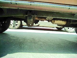
This project meets the criteria for my "Cheap Tricks" section, it was fairly cheap (unless you add the cost of the way-cool plasma cutter) and it was definitely tricky :-). So what does a 2" drivetrain lift buy you? Take a look at the photo below:
I didn't get a shot of the before state, but have a look under an 1st-gen 4Runner and compare. FYI: The nerf bars are 2" square tube. You can see that the gas tank skid plate hangs down about 1" below the frame and the transfer case skid plate perhaps 2" at its lowest point. BTW: I did manage to scrape the skid plate, so this is not a cure-all for clearance by any means. However, I would like to point out that I never was aware of scraping the skid plate, I never got hung up or high centered like I used to on the stock crossmember. Scraping things meant to be scraped is fine by me (bumpers, nerf bars, skid plates, etc.) but scraping things not designed for that abuse or getting hung up on stuff is not.
[Return to the top of this page] [Return to my Cheap Tricks page]
[Author: Roger Brown]
Visitor # 107726 since 18.APR.2001
[Last updated: 11.January.2025 ]
