Under Bed/Dual Battery Installation
Contents:
![]()
Introduction:
When I first started building my truck for wheeling, *the* thing to get was the Optima red-top battery. So I got one and replaced the aged lead-acid battery that was leaking all over my fender. Seemed like just after that, *the* big thing was dual batteries. My single red-top filled the area under my hood and worked fine for nearly two years of hard wheeling, but after picking up a Premier Power Welder, I had to find some room to install the large control box for the welder.
So, what you might ask, does needing more room under the hood and dual batteries have in common? Well, needing more room led me to explore alternate locations for some of the equipment already living under the hood. I ruled out the engine electronics, my 12V air compressor and that basically left the battery. Batteries are big and heavy, so I thought if I could find someplace low and out of the way for the battery, I could free up valuable space, lower my center of gravity and get my welder installed.
Here were my design goals:
-
Dual batteries with high-current and deep cycle capabilities
- Improved winching capabilities
- Allow for 12V accessory use in camp
- Provide redundant starting power supply
-
Relocate battery from engine compartment to frame area
- Lower center of gravity
- Free up valuable under-hood space (for welder control box)
-
Allow for flexible power connections
- Support for batteries in series (for emergency welding)
- Front and rear power connections for jump starting
- Easy to disconnect batteries for servicing
Installation:
So, to start the process, I used the highly scientific method of a creeper and a tape measure and basically measured the dimensions of all the likely spots under my truck where a battery might possibly be attached. I had not yet picked a battery, but I had a few types I had dimensions for and then checked the available locations to see if the battery volume would fit. Besides the location I found, below, I also noted that the area above the rear axle is quite open and would also make a good battery location, although I plan to install either a 2.5 gallon air tank or an air bag helper spring there.
 |
 |
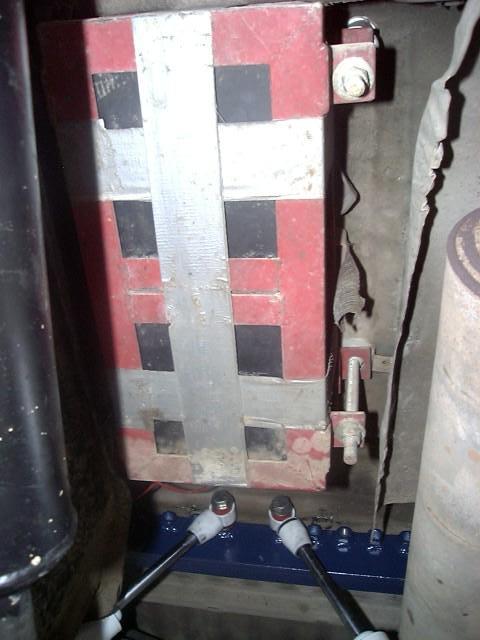 |
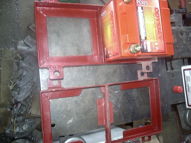
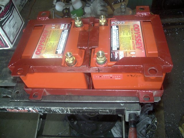
| A: Battery tray parts | B: Battery tray assembled | C: Battery tray installed |
Lo and behold, I found a location for two small batteries up above the rear drive shaft, below the passenger seats. The battery tray is made of 1x1x1/8 steel angle, cut and welded into a frame as shown in photo A above. The bottom tray has two square recesses for the batteries, the top frame is the same except with the top web cut out to clear the battery terminals, as shown in photo B above. I actually welded the top and bottom trays up at my old welding class. I purchased all the steel angle at a local hardware store, them pre-cut all the pieces ona table saw equipped with an abrasive cutoff wheel. Then took the bag of parts to class and spent most of the night gas (oxy-acetylene) welding the parts together. I figured why spend 3 hours welding scraps of steel together that would be tossed into the scrap bin afterwards, when I could make something useful instead! Had a great welding teacher and he was cool with students doing their own thing.
To attach them, I used 4 threaded rods that hang from the floor. I drilled 4 holes in the floor pan beneath the rear seat bottom. A lock nut and heavy washer on the top of the floor supports the weight, another nut snugged up against the bottom of the floor panel, with a length of pipe to serve as a spacer, holds the threaded rod tight. Then a third nut holds the battery try in place from below. In photo C above, you can see the threaded rods running along the side of the battery tray. And what is that silver/gray stuff wrapped around the tray? Looks like duct tape and that's what is is. I used the duct tape to strap the upper and lower trays together while I slid it up onto the threaded rods, that in turn pass through holes in tabs welded to the sides of the trays. Once the nuts are tightened down, the trays clamp the batteries in between them snugly and nothing can move. As it is, the pair of batteries are sandwiched between the gas tank and the heat shield above the muffler.
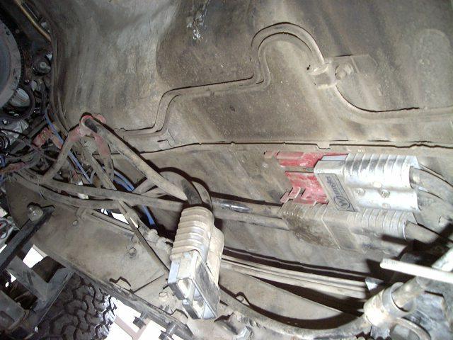
There's not a lot of room, but the tiny BP-800MJ Black Panther batteries don't take up much more room than a single conventional battery. After about 9 years of trouble-free service, I took the opportunity to replace the pair of Black Panther batteries (no longer available) with an identical size/capacity unit from Odyssey, a PC925 model. As an added benefit, they are totally metal jacketed and completely sealed, so should be up to the harsh environment down there. The batteries are bolted up through the floor, and 1/0 welding cable is used to bring the power up, under the body to a pair of 350A disconnects, pictured below:
These disconnects serve several functions:
- The main and auxiliary battery may be swapped with the disconnects (since their terminals are inaccessible) to equalize their service life
-
The engine and/or aux. power may be cut for working on the engine (see
#1)
- Pictured above, I have the engine power disconnected
- I also ran a new 1/0 cable directly to the starter, this made a huge improvement in starting torque
- The batteries may be hooked up in series for DC welding, if needed, since they are "floating"
The grounds are tied together after the connectors and the positive leads terminate on insulated studs (these can be seen at the far left of the image above). A pair of 1/0 cables run up to a 200A continuous duty solenoid which can be controlled in a number of modes. I ordered both batteries at the same time, so hopefully they'll be out of the same lot. This is important to minimize problems with the two "fighting" when in parallel. Also, these batteries are true deep-cycle units and can be deeply discharged without damage.
- The purpose of the solenoid is to isolate the two batteries from each other when the engine is not running. Even with two identical batteries, they can have slight internal differences in charge and resistance that could cause them to self-discharge when the alternator is not supplying power.
- Another option for this function is a battery isolator. This is a solid-state device that uses diodes to isolate the batteries from each other. While an isolator is ideal for isolating a deep-cycle RV-type battery for aux. power use, its inherent voltage drop makes it less than ideal for use in high-current situations like winching and crank starting.
- Then there are even more sophisticated isolators that include relays internally to bypass the solid state devices when needed.
The main battery is tied to the engine fuse box, while all the auxiliary circuits (including the winch) are fed from the auxiliary battery. A disconnect on the front of the vehicle supplies the winch or a jumper cable. A connector in back serves a similar function. But, you may ask, doesn't an electric winch draw a lot of current? Yes they do, easily more than the 200A capacity of the solenoid, but not all 400A going to the winch comes through the solenoid. Ideally, 200A of it would come from the auxiliary battery (before the solenoid) and the other 200A from the main battery (via the main battery). Practically, a bit more may come over the solenoid since the 160A alternator is behind it, too. But in several years of use, I've not had any problem with the solenoid or winch operation. A solenoid current rating is typically determined by the amount of current it can make or break, the actual running current can be much higher in practice, as long as I don't try switching the solenoid on or off while at full pull on the winch.
The solenoid control logic, from Painless Wiring, allows for 3 modes of operation:
- Mode one is used for most conditions. In this position the system has twice the normal starting amperage automatically. Batteries are isolated with the ignition off, thus preventing the "dueling battery syndrome". When the ignition is on (and the engine running) both batteries are charged (in parallel) from the alternator.
- Mode Two is provided to lock out the auxiliary battery. In this mode the secondary battery can be held in reserve when heavy winching or extended cranking are expected. Or, in my case, I have the winch connected to the auxiliary battery, so this way the winch will not drain my main battery. In this mode, the main battery is charged by the alternator, but not the auxiliary one.
- Mode Three is used if the main battery won't start the vehicle. This mode allows a self jump-start from the auxiliary. Both batteries are charged by the alternator in this mode, however, the solenoid remains energized even if the engine is off.
While it seems that this is a very primitive and simple circuit, I find its remarkably effective and easy to use, or should I say not use. In day to day use, you never touch the switch. In fact there are probably entire years that I don't touch the switch or even think about it. Its just left in the Mode 1 setting, which turns on the solenoid when the ignition is on, putting the two batteries in parallel. When the engine is shut off the solenoid automatically turns off, separating the two batteries. Only on the rare occasion I kill the main battery, instead of hauling out the jumper cables and finding a willing battery donor, I just flip the switch to Mode 3, wait a few seconds for the aux. to charge the main, turn the key and start the engine. After a few seconds, flip the switch back to Mode 1, where it'll stay for another year. Have never needed Mode 2 other than to feel how slow the starter turns with one instead of two batteries. Now I only carry jumper cables to jump someone else (if needed) or to rig up a 24V output for welding purposes.
I've slightly departed from this recommended setup, by placing all my auxiliary devices, like winch, power points, CB, lights, etc. on the 2nd battery. Since I use a 12V DC cooler, I want to be able to run it all night off the 2nd battery and not have to worry about draining the main battery. Anyway, the idea is that in normal operation, ignition power energizes the solenoid to connect the batteries together, for charging and double starting current. With the ignition off, the batteries are separate. The jump start mode allows the solenoid to be energized manually.
For safety and convenience, I made up a pair of 5' extension cables, with a 350A connector shell on each end as well as a pair of 5' jumper cables (with a 350A connector on one end and battery clamps on the other end). I'll be installing a similar, single battery system in my pickup and intend to share these cables with it. For emergency welding, I can unplug the two battery connectors, plug in extensions and jumper cables, tie one "-" to the other "+" lead and obtain 24V DC from the remaining clamps. While I plan to have a Premier Power Welder to do the main welding chores, for the price of a few connectors and some cable, I can provide a backup welding system, so why not add it to the system? The front and rear connectors allow for safe battery jumping (no battery fumes to explode) and it just so happens that the quick disconnects that portable winches use are the same as I used, so if needed, I can hook up a portable to my rear bumper.
So, now with the battery out of the stock location, I also decided to move the air box into this place and then place the PPW control box where the air box used to live. The battery control switch lives up next to the formerly empty switch location on the dash. I had previously moved the rear window control switch into this location.
After about 10 years of use, the old Black Panther batteries started getting a little tired. With the small 25AH capacity, it did not take leaving a lot of stuff running to drain them. So I picked up a pair of Odyssey batteries of the same size and swapped them out. I figure to get another 10 years out of this pair. Surprisingly, when I got the BPs out, I found they still held a charge fine. I think the main source of the problems was that one of the posts had loosened up. After getting an allen wrench inside to tighten up the retaining screw, that battery seemed fine. But since I already swapped in the new ones, I put the old batteries to use in my solar heating/cooling setup in my house. Solar panels charge the batteries and a thermostat operates a fan that either pushes sun-heated air into the house, or pulls cool night air in. So those batteries are now in their second "career" and enjoying a second life!
I am really happy with this dual battery setup. It is very reliable, have not had one problem with in since installation. And with the long lifetime of the batteries, they must "like" it too. If not, they would not last that long. I never even think about the dual batteries in day to day use. They are just there, just like one battery. The only time you think about it is if for some reason the main battery gets drawn down too far to start the engine. In that case, instead of popping the hood and dragging out the jumper cables, I just flip a switch on the dash and off I go.
In this system, both batteries are wired up with equal length cable and connections. The only difference in current path between the two batteries for charging and discharging is the contact in the solenoid. Some issues others have had with solenoid based split charging systems may be due to having the aux. battery at the opposite end of the vehicle and there's much longer and possibly under-sized cables along with multiple wiring connections between the solenoid and that aux. battery. This can lead to under charging the aux. battery.
[Return to the top of this page]Parts List:
Excuse the "crude ASCII art" but this is how it is all hooked up:
Wiring Schematic

       +---------------------------------------------+
       |                            AUX              |
       |>----------------------------+--------------<|>-+
       R                  Batt2-<>---+               F  |
       E                            SOL              R  W
       A                  Batt1-<>---+---ALT         O  I
       R                             |               N  N
       |                             |+-<>-STR-FUSE  T  C
       |                             ||              |  H
       |                             ++              |
       |                                             |
       +---------------------------------------------+

       2 - 6' extensions   2 - 6' jumper cables
       >------<  >------<  >------C  >------C
- Legend:
-
">" is a 350A connector shell
- "STR" is the starter
- "FUSE" is the engine fuse block (internal 80A fuse)
- "SOL" is the 200A solenoid
- "AUX" is the auxiliary fuse block
- "ALT" is the 160A Premier Power Welder Alternator
- "WINCH" is the Warn 9000i front-mounted winch
- Note: Ground circuit omitted for clarity, but ground cables are run in parallel w/ power to minimize ground loops.
- "STR" is the starter
-
Parts Supplies: -
Wrangler Power ProductsPainless Wiring ProductsPremier Power Welder- Madco Welding, Mtn. View, CA.
Part List for dual battery wiring
| Part | Description | Qty |
| 34-902G | 350A Connector Shell | 15 |
| 32-902-1 | 1/0 terminals | 30 |
| 34-902DC | Dust Cover | 1 |
| 34-902M | Connector mounts | 2 |
| 34-902L | Connector locks | 2 |
| 30-101CR/B | Positive power studs | 4 |
| 32-6410-38 | Cable lugs | 10 |
| 32-4110P/N | 1/0 battery clamp | 2 |
| 32-4210P/N | 1/0 battery clamp | 2 |
| 32-317R/B | Battery clamp insulator | 2 |
| 32-318R/B | Battery clamp insulator | 2 |
| 32-653B/R | 1" Heat shrink tubing | 4' |
| 34-915B/R | 350A battery clamps | 4 |
| 38-101 | 1/0 terminal crimper | 1 |
| 1/0 | Welding cable | 50' |
| BP-800MJ | 800A Batteries | 2 |
Rating: ![]()
![]()
![]()
Welding with Batteries:
So, can you really weld with a couple of 12V batteries?Yes, quite well in fact. I find 3 in series (36V) work better that 2 (24V) but in a pinch use what you got. You'll need some welding rod, a rod holder (jumper cable clamp might work in a pinch) some jumper cables and some batteries. If everyone in your wheeling group has a set of jumper cables, you are set. Hook cable to each battery, then connect the red of one to the black of the next one and so on, finally ending up with one black clamp and one red one and 24 or 36V between the two. Keep the batteries as far back from the welding location as you can, especially if they are not sealed units. A fire extinguisher is a good idea and some basic welding safety equipment like heavy gloves and a face shield with minimum #10 tint lens.
So what kind of rod should I get:
Shielded Metal Arc Welding rods are designated by a multi-digit code as follows:
-
ESS(S)PC
- SS(S) is the tensile strength of the filler material (in Kpsi, 60 = 60,000psi, 70=70,000psi, etc.)
-
P = Recommended welding position:
- 1 = All positions
- 2 = Flat or Horizontal
- 4 = Flat, Horizontal. Overhead and Vertical (downhill)
-
C = electrode Covering composition (combined with
position
- 10 = High Cellulose Sodium
- 11 = High Cellulose Potassium
- 12 = High Titania Sodium
- 13 = High Titania Potassium
- 14 = Iron Powder, Titania
- 15 = Low Hydrogen, Sodium
- 16 = Low Hydrogen, Potassium
- 18 = Iron powder, Low Hydrogen, Potassium
- 20 = High-iron oxide
- 22 = High-iron oxide
- 24 = Iron powder, titania
- 27 = High powder, high-iron oxide
- 28 = Iron powder, low-hydrogen, potassium
- 48 = Iron powder, low-hydrogen, potassium
| AWS Classification | Covering | Position | Current Type |
| E6010, 60K psi | High Cellulose Sodium |
F, V, OH, H |
DCEP |
| E6011, 60K psi | High Cellulose Potassium |
F, V, OH, H |
AC, DCEP |
| E6012, 60K psi | High Titania Sodium |
F, V OH, H |
AC DCEN |
| E6013, 60K psi | High Titania Potassium |
F, V OH, H |
AC DC-any |
| E6014, 60K psi | Iron Powder, Titania? |
F, V OH, H? |
AC DC-any? |
| E6018, 60K psi | Low Hydrogen Potassium Iron powder? |
F, V OH, H? |
AC DCEP |
| E6020, 60K psi | High Iron Oxide |
H-fillets F |
AC DCEN |
| E6022, 60K psi single pass only |
High Iron Oxide |
F | AC DC-any |
| E6027, 60K psi | High Iron Oxide, Iron powder |
H-fillets F |
AC DCEN |
| E7014, 70K psi | Iron Powder, Titania |
F, V OH, H |
AC DC-any |
| E7015 70K psi | Low Hydrogen, Sodium |
F, V OH, H |
DCEP |
| E7016 70K psi | Low Hydrogen, Potassium |
F, V OH, H |
AC DCEP |
| E7018, 70K psi | Low Hydrogen Potassium Iron powder |
F, V OH, H |
AC DCEP |
| E7024, 70K psi | Iron Powder, Titania |
H-fillets F |
AC DC-any |
| E7027, 70K psi | High Iron Oxide, Iron powder |
H-fillets F |
AC DCEN |
Notes:
-
Position:
- H = Horizontal
- F = Flat
- V =
- O = Overhead
- OH = Overhead Horizontal
-
Current:
- AC: Alternating Current (not applicable to battery welding - although most AC rods work on DC-any))
-
DCEN: Direct Current, Electrode Negative
- Also known as Straight Polarity or DCSP
-
DCEP: Direct Current, Electrode Positive
- Also known as Reverse Polarity or DCRP
- DC-any: Direct Current, any polarity (i.e. rod can be used DCEN or DCEP)
Regarding current/polarity, the "electrode" of course is the welding rod. If its positive, DCEP for example, then the work piece is hooked to the opposite polarity, or negative. This would be the "normal" type of welding on a vehicle, frame grounded, and the welding electrode positive. Typically you want to attach the ground clamp on clean bare metal, close by where you are welding. To be safe, disconnect any sensitive components like engine computers or sensitive electronics prior to welding.
From the above chart, you can see but some of the many choices available. What you get depends on what you'll be welding, what you are used to, what you can find, etc. I carry the following:
- 6010 - 1/8" - Deep penetration, fast freezing, good for rusty/dirty metal
- 6011 - 3/32" - Works well for overhead
- 6013 - 3/32" - Works DC-any, so I can use DCEN for reduced penetration on thinner steel
- 7018 - 3/32 & 1/8"- Best for high-alloy steel and is higher strength
If you don't know how to weld, take a class at a local community college or adult education facility. I take classes two nights a week at the Central Coast Occupational Center (CCOC) in San Jose, CA. A full semester of classes costs about $275 and you get nearly unlimited access to every kind of heavy-duty industrial welding equipment you can imagine. You get spoiled with 100% duty cycle machines.
Then, once you have the basics down, hook up some batteries and practice in your driveway. Go ahead and weld some real parts to your truck. My first project was welding a plate to the inside of my frame rail to reinforce the power steering box mounting. Then, I added a few beads to my rear spring hangers and then welded on new front spring hangers and finished up with some heavy, reinforced spring shackles made out of 3/8" steel. That's where the 1/8" 7018 rod came into play, It made a nice one-pass weld in that thick stock.
- Some welding related information
- Safari4x4 has an excellent primer on the subject
- Another interesting option for battery-powered welding is the Ready Welder portable MIG unit
- If you want something more than batteries for welding, check out my on-board welder writeup.
[Return to the top of this page] Back to my Cheap Tricks main page.


[Last updated: 19.March.2022 ]
Visitor # 188412 since 28.AUG.2001