Toyota 4Runner and Pickup: Waterproofing Tricks
![]()
Here are some cheap tricks for making your Toyota 4x4 more waterproof.
Contents:
- Differential Breathers
- Wheel Well Liners
- Electric Fan with Manual Controls
- Air Intake Snorkel
- Raise the engine computer (ECU)
- Transmission and Transfer Case Breathers
Differential Breathers:
What's a differential breather and what do they do? On most vehicles with axles and differentials, there is a need to vent the axle housing to the atmosphere to allow for the air inside to expand and contract with temperature. If this were not done, the pressure in the axle would build up as it heated up, possibly causing gear oil to be forced past the oil seals. Similarly, when the axle cools, the pressure inside drops and if the axle were in water, this could suck water in past the seals, contaminating the oil.
So correct this potential problem, the factory usually installs a breather to allow the pressures to equalize. The Toyota breather consists of a nipple that threads into the top of the differential housing and a small cap that loosely covers the vent hole. The cap is designed so that as the vehicle moves, the cap jiggles and allows pressure to vent to the atmosphere. When the vehicle stops, it usually seals up to prevent contaminants getting in. One problem can come up with this design that if you suddenly dunk a hot axle into cold water and stop, a fairly strong vacuum is created inside as the air and gear oil cool, and this can cause water to be pulled in. A very common fix for this problem is to replace the stock breather with a fitting to which a hose is attached and run the hose up to a higher point on the vehicle, like the firewall or air cleaner. This allows the axle to breathe freely in or out to prevent pressure differences from occurring.
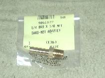
So, one might be tempted to simply pull off the cap and clamp a hose onto the end. While this will work (for a while) the exposed fitting is very short and irregular and keeping a hose attached is difficult. So, various other types of fittings have been used to replace the stock fitting. One commonly used fitting is a vacuum hose nipple similar to what is used on the engine. Another popular fitting is the Nissan differential breather part # 38323-C6010; cost around $4.50/ea.
However, the threaded hole in the Toyota axle is nothing more than 1/8" NPT:
- NOTE:
-
Officially I would think the thread is either M10-1.0 or 1/8" BSP
but its close enough for gov't work :)
- NPT = National Pipe thread Tapered, and it is 0.407" (10.2mm) OD with 27 TPI (threads per inch)
- M10-1.0 is 10mm OD and 1.0 mm thread pitch (or 25.4 TPI)
- BSP = British Standard Pipe thread, and it is 0.407" (10.2mm) OD with 28 TPI (threads per inch)
- So you can see the three are VERY close and for the few threads in the housing and the fact that pipe threads are tapered (meaning the male thread starts out small and gets larger in diameter as it threads in, female thread is the opposite) an 1/8NPT thread fits fine for this low pressure, low stress application, YMMV.
- For an even better fit, run a 1/8" pipe thread tap down into the housing, apply grease to the tap to hold the few metal shavings it'll cut.
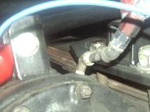
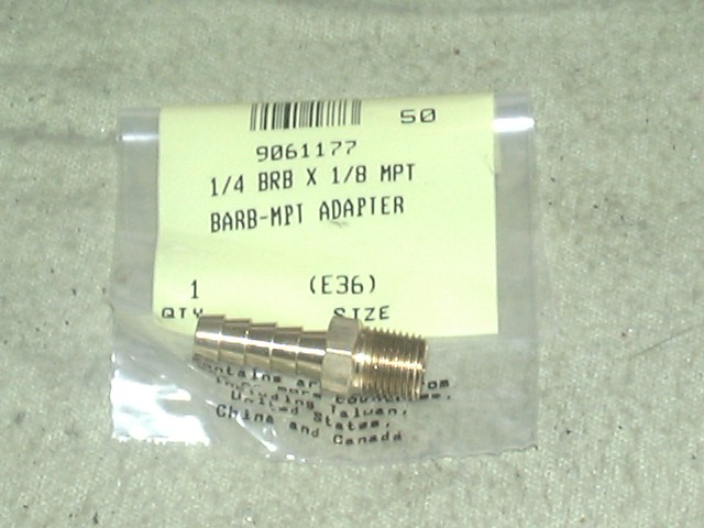
Straight 1/8NPT to 1/4 barb
fittingA 90 degree 1/8NPT Street Elbow
installed in the front diff.A trip to the local hardware store revealed a whole wall full of every conceivable type and style of fitting for 1/8" pipe thread. They have NPT to hose barb fittings, NPT to NPT nipples, elbows of all sorts and they all cost around $1. For the rear axle, a simple NPT to hose barb fitting, sized for the ID of the hose you intend to use is ideal. Up front, I found the use of a close nipple and a 45 degree elbow and a hose barb makes a good combination.
So, what do you do with them once installed? Up front, hook up a length of hose and terminate it at a filter on the firewall, as high up as you can get it. In back, I first ran up to the front line and filter, but found in cold weather that gear oil collected in any low points of the line, and essentially plugged the vent, letting pressure build up in the axle and forcing oil out past the seals. Then I routed it to the rear and up onto my rear tire carrier, as pictured here.
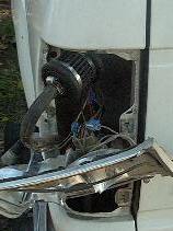
After selling the rear bumper, I had to find a new location for the filter. I found that if I pushed the hose up inside the rear tail light housing, I could re-install the filter (pictured above). No drilling or cutting required. Now that's a really cheap trick! I've found the tail light housing seems to stay very dry, just a little dist inside. With the filter pushed clear to the underside of the bed rail, I would have to be in some deep water to submerge the vent line.
- NOTE:
- The following mental experiment should help see if your vent line run is proper. Imagine you will try to fill the axle with gear oil by pouring it into the end of the hose where you have the filter. If you feel that you could fill the axle with oil from the end, that is it would run downhill all the way from the filter to the axle, then its probably OK. If there are any points in the line run where you have a dip in the run (such as wires between power poles) then oil can pool there. Gear oil is thick and when cold it is VERY THICK and doesn't flow well at all. While the oil in the axle will heat up with use and flow easily, any oil pooled in the vent line won't heat up if its cold outside. I found when my line plugged up with oil in cold weather, pulling the vent line off the axle and blowing into it took a pretty strong puff or air to blow the line clear (like blowing into a straw in a thick milk shake). That much pressure buildup can force oil out past the axle and pinion seals.
The idea behind the breather is to place the end of the line as high as you can get it, in a protected location where its not going to get pelted with mud, dust and water. Some folks carry this to an extreme and route the breather lines as well as the vehicles air intake up to a snorkel. This, in theory, would let the rig ford water up to the point the top of the snorkel went under water. This assumes you have EVERY OTHER water-sensitive part of the rig waterproofed in some fashion. In fact, there are some folks who have done all this and find that doing so creates a secondary problem, that being that the vent is so high up, that you get significant water pressure buildup (1/2 psi per foot of water depth) that water gets into the axles, despite the vent. So what then? You need to run the axle with a slight positive pressure maintained with a small on-board air source. Certain military vehicles are so equipped.
So where does it all stop? It all depends on how much time and work you want to put into it and how much you need to run in water. Do as much as you can, based on what sort of conditions you drive in. I don't purposely drive my truck in mud or water, but if a water or mud crossing blocks the trail and is the only way across, then I have to go in. In many years of 4-wheeling, I've never had water get in my axles, never had to change gear oil because it got contaminated, so I think a simple vent like I have works good enough.
- Cost:
-
About $1 per axle
- Rating:
-
 /2
/2

Wheel Well Liners:
After I bought my 4Runner (used) I noticed the passenger's side wheel well liner was almost ready to fall off. I replaced some of the missing plastic snaps and then noticed the driver's side was missing all together. After doing my 1" body lift, it became obvious that the liners needed to be replaced, since they no longer provided useful protection. The liners can help reduce the amount of water and mud that is thrown up by the front wheels into the engine bay. They won't keep the engine totally dry, but every little bit helps.
I found a company that makes custom fit "Lift Lips" out of heavy gauge neoprene rubber for Toyota trucks. The rubber is over twice as thick and will not tear like the stock material. They are supposed to fit up to 3" body lift, so I found I needed to trim a bit of rubber around the shock towers to get mine to fit. I also found it necessary to cut a slot for the brake line to fit through.
One thing I did notice, was that the plastic snaps supplied with the kit fit the stock holes very loosely. I found that a #10x24 threaded insert will fit the stock holes (a few needed a pass of a 9/32" drill bit) nicely. I then used brass screws and washers to attach the liners. Now, the liners are very secure, yet easily removed if needed (like changing oil and fuel filters). Not sure if LiftLips is still in business, but here's the last information I had:
Lift Lips
Mountain Enterprises
P.O. Box 890311
Temecula, CA 92589
Cost:
   Lift Lips ................ $50
   Threaded inserts (~30) ...  15
   Brass screws/washers .....  10
   ------------------------------
   Total .................... $75
Rating:
 Electric Radiator Fan and Custom Controls:
I replaced the stock belt-driven fan and clutch with an electric Flex-A-Lite Black Magic Fan. The fan is designed for drop-in replacement of the stock fan. To install it, you remove the air intake tube and the top radiator hose. Remove the 4 bolts holding the fan clutch to the pulley the the stock fan shroud. The new fan brackets mount to the existing shroud mounting holes. A rubber gasket surrounds the new shroud and seals it against the radiator. An thermostat bulb also contacts the radiator and is adjustable.
After installing the fan, I noticed its control module has some auxiliary inputs to allow for some interesting features (you can access the on-line installation instructions fromt eh Flex-A-Lite web page above). I was inspired by my work on my VW pickup where I modified the factory electric radiator fan. With the base installation, the fan will only run when the its thermostat trips. For a reliable off-road vehicle, I felt some functional additions were in order. (Besides I'm an electrical engineer and can't resist tinkering with things electrical:-)
- The module has an A/C input (the "C" terminal) to turn the radiator fan on while the A/C is operating. I tapped into the hot wire of the A/C compressor clutch for this function. This way the fan is only operated while the compressor is actually running. This is handy in town when stopped, there is still fresh air flowing over the A/C evaporator coils. I did have to tweak the setting on the A/C cutoff controller behind the glove box to keep the A/C running at idle.
- There is a pair of low-current +12V inputs; one that enables automatic operation (the "+" terminal - via the built-in adjustable thermostat, initially, I had just tied this input to +12V). The second input allows manual operation of the fan (this is the "M" terminal). I simply connected these two inputs to a dash-mounted single pole double throw (SPDT or ON-OFF-ON) switch which in turn was wired to a fused 12V source. That is, I connected 12 volts to the center terminal of the switch and wired the terminal that is on with the swith UP to the "+" terminal on the fan controller and the DOWN switch terminal to the "M" termina on the fan controller. In the UP position, the fan is in automatic (i.e. thermostat) mode as 12 volts from the switch is connected to the "+" terminal on the fan controller, in the center, it is off (handy for deep water crossings - since no power is conected to either the "+" or "M" terminal on the fan controller) and in the DOWN position, it is in manual mode (i.e. always on since power is being sent from the switch to the "M" terminal on the fan controller). The switch it tucked up under the ash tray next to an indicator light (#3). Click here for a simplified wiring diagram of the above setup.
- I somehow distrust automatic things and like to know that they are actually running. The electric fan is no exception, so I spliced a wire to the hot side of the fan motor (this is the wire that runs from the fan control module to the fan motor itself) and ran it to a 12V indicator lamp that I installed next to the switch (#2). This way, whenever the fan motor is running, the light illuminates. This is quite useful to see if the thermostat setting is high enough to keep the fan off during highway driving, and low enough for stop-n-go traffic and 4WD Lo rock crawling. Also, with the A/C input (#1) you can also see when the A/C compressor is running.
- Cost:
 Assuming you already have the electric fan
  - (mine was $200 on sale at Perf.Prod.)

  SPDT toggle switch   $5
  12V indicator light   2
  Misc wire/connectors  3
  -----------------------
  Total               $10
Rating:
- some knowledge for electricity required.
NOTE: If you do install a switch with an OFF position, as described above, this really means OFF, as in the fan WILL NOT COME ON, no matter how hot the engine or coolant. Be very careful with the fan switched off and you may want to consider some sort of guard over the switch to prevent it from being accidentally turned off. I once had a Toyota dealer mechanic call up and say my fan was inoperative and needed to be replaced. He had been fiddling around (I suspect) and had turned off the fan before starting the engine. I had purposely not labeled the fan switch, but even so, it was "messed with".
[back to the top]Relocated Engine Computer:
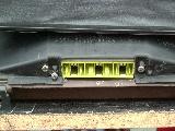
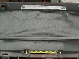
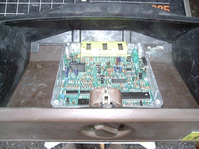
On Toyota's with electronic fuel injection (EFI) the engine control unit (ECU) is a critical component of the truck. If it gets wet, it is likely to stop working. The ECU box is not sealed and doing so would be a difficult process. In my '85 4Runner, the ECU is located in the passenger foot well, behind the small kick panel. It is placed just off the floor, so if any water were to enter the cab via the door seals, chances are the ECU would get wet. I decided it might be a good idea to try to raise it up as high as possible using the existing wiring harness. With all the HVAC ductwork and whatnot behind the dash, there is no room to mount the ECU in there, so the next logical place was the glove box.
1.
 2.
2.
3.
 4.
4.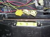
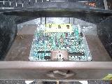
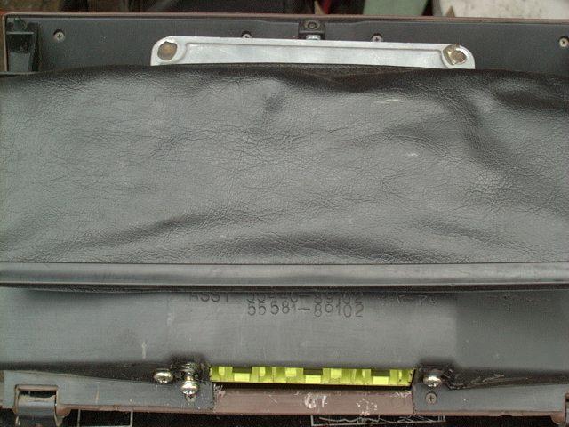
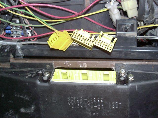
In picture #1, you can see the ECU fits nicely, I removed the top cover so I could mark for the connector cutout and the mounting holes. In picture #2, you can see the cutout for the connectors, note that the 14P connector is on the left in this picture. When the glove box is ultimately reinstalled, this places it to the right since the 14P cable seems to be the shortest on my truck. In picture #3, you can see the ECU tucked inside the glove box, connectors out the bottom, and the top of the box just protruding above the back of the glove box. Unfortunately, you can't mount the ECU flush to the back of the glove box, since it'll hit some of the ductwork that is just behind the box. I left the ECU standing vertically off the bottom of the glove box and this gives it enough clearance for the duct. FInally, in picture #4, you can see the 3 connectors ready to plug into the ECU.
It may not seem like much, but this simple relocation raises the ECU a full 12" (one foot!) from the factory location. I found little loss of glove box volume with the ECU in there, still enough room for all the "junk" I had in there before. Now this places my ECU about as high as my engine air intake and differential breathers.
[back to the top]Transmission and Transfer Case Breathers:
In stock form, my W56 transmission and RF1A transfer case(s) are vented through the shifter, there is no separate vent as exists on some other Toyota gear box designs. This presents a few problems, the obvious one is if the shifters are submerged in water, as the gear box cools and the air inside contracts, water will be sucked inside. The second, and less obvious problem is that gear oil smells and the venting fumes can often enter the cabin area, this is a more common occurrence since having dual transfer cases installed with less then perfect sealing.
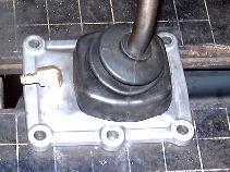
So to fix this, I simply removed the shifter base off the gear box, drilled and tapped a hole for a 1/8" NPT fitting and installed a 90 degree NPT to hose barb fitting. Then I later used some sealant around the top of the inner rubber shifter boot to help seal it up from water entry. Once all the vents are in place (still working on the transfer case vents), I'll tie them all together with tee's and run a line up forward to the firewall and install a filter for the end of the vent line.
[back to the top]Visitor # 165356 since 12.NOV.2001
[Last updated: 22.March.2021]
- NPT = National Pipe thread Tapered, and it is 0.407" (10.2mm) OD with 27 TPI (threads per inch)


 ===>>
===>> 