 |
 |
Body Lift Installation Instructions
Save a tree, click here to download an Adobe PDF file of these instructions
Contents:
- Preface
- Recommended Tools
- Safety First
-
Installation/Vehicle Specific:
- Body Lift Removal
- Body Mount Bushings
-
Toyota 4Runner, see also:
- 2nd Gen ('90-'95) 4Runner
- 3rd Gen ('96-'02) 4Runner
-
4th Gen 4Runner and FJ Cruiser
- Good overall writeup: HTML - or - PDF
-
Steering shaft extension installation and VSC adjustment: HTML - or -
PDF
- Includes information applicable to the 2005+ Tacoma and Tundra steering shaft extensions as well.
- Steering shaft extension photo album: Google Photos
- This has details on the installation of the riveted steering extensions, etc.
- Toyota 2WD/4WD Pickup, see also:
-
Toyota Tacoma ; see also
- Body lift removal video on YouTube: https://www.youtube.com/watch?v=KR8s4YFBn9k&list=PLzFRfcJOUl6g5FfO7GIYfO7elxpZNRh5P
- 1995.5-2004 models:
- 2005+ models
- Toyota Landcruiser
-
Mitsubishi Pajero/Montero, see also:
- http://www.cap510.com/bodylift.html
- MonteroBodyLiftInstall.txt
- For MightyMax and D50 pickup models, see Montero section for cab, and the Toyota pickup section for the bed.
- Kia Sportage:
- Nissan Frontier: http://www.clubfrontier.org/forums/f23/2-body-lift-install-guide-70883/
- Isuzu Rodeo: http://www.planetisuzoo.com/articles.htm?id=106
- Installation/Optional Items, as required:
- Caveats and Pitfalls
- Difficulty and time estimate
Preface:
These instructions are intended to cover most aspects of the 4Crawler Offroad body lift kits on a variety of vehicles. Also included below are links to vehicle-specific installation write-ups. Feel free to browse those links for additional information. Also, if you run across other web write-ups that you find useful or you have specific suggestions for improving the installation notes on this web site, please forward that information to 4Crawler Offroad. This document is constantly evolving based upon user feedback, so if there is anything you would like to see improved, clarified, etc. send it on!
- Note:
-
Almost all purchasers of our body lift kits install the kits
themselves. The kits have been designed for easy, DIY installation, but
if you lack the skills, time or location to do the installation
yourself and are considering having a shop do the installation, be sure
to bring a copy of these instructions to the shop. Since the 4Crawler
Offroad body lift kits cover a wide variety of vehicles, many of which
there is no other body lift kit available on the market, your shop may
say they can't do the installation on your vehicle, since to their
knowledge, no such kit exists and/or they are not familiar with the
4Crawler Offroad lift kits. For example, you may have a Toyota 4WD
vehicle with an automatic transmission. Most shops will tell you that a
body lift can't be installed on such a vehicle. While this may be true
with the big name-brand kits, 4Crawler Offroad has been shipping kits
for automatic transmission vehicles since 2002 when the AT bracket kit
was developed due to customer request. In fact, literally thousands of
kits have been installed, with simple hand tools, over the years and
are working just fine on Toyotas with automatic transmissions.
- If considering having a shop install your body lift kit, you might want to locate a shop and get a commitment to do the installation prior to ordering the kit. No sense getting your custom built lift kit in the mail only to have to return it due to not being able to find a shop to install it. Why the problems? Well in these days of everything being computerized and "by the book", if some task is not listed in the standard rate shop time book, the shop may not be able to "figure out how much time" to quote for the install. After all that would require some thinking on the part of the shop owner. If you want new shocks or a new muffler or a new alternator installed, they just punch in the code for that job and out pops a time and there is your estimate. So, instead of hitting the big chain repair shops, try and find a local "mom and pop" shop where you can talk to the owner and operator and work out a deal for the installation. And if you can't find a local shop, check for a local 4x4 club, mailing list or web forum and see if you can find a local buddy that has more experience than you do to give you a hand. Maybe all you need is to borrow a friend's driveway, car port or garage to get a place to do the work. You may only end up being out a case of your friend's favorite beverage.
And finally, please read through or at least skim the entire set of instructions to familiarize yourself with the sorts of things you may run into on your particular vehicle. Also keep an eye out for things you may need to do prior to installing the lift, such as loosening the steering shaft clamps/bolts, or checking radiator/fan clearances, etc. Since vehicles vary both in makes and models as well as modifications that may or may not be present, it is hard to give an exact step by step installation process. So, scan over the instructions, read those sections that pertain to your vehicle and then plan out a strategy for installing the lift. Also, don't be intimidated by the length or detail of this document. While we may describe half a dozen approaches to a given issue you may encounter, you will not need to do all half dozen "fixes". Rather, you'll just find the one fix that solves your issue, do that and proceed. So just be aware that we have tried to document all the issues all our customers have run into over the years along with ours and their approaches to fixing each issue. By the time you get to lifting your vehicle, it has undergone it's own history of use and modification, and thus each body lift install is going to be somewhat unique. So rather than try to provide a linear series of steps that everyone follows the same, we try to lay out the general process and then deal with the various little issues that may crop up as you go. We have all read and tried to follow those assembly instructions where you have to put bolt 41 into hole A of bracket Q and install washer T and nut Q using tool X. You get to the end and have a pile of parts left over and no idea where you messed up. But feel free to check out the various web page links that we have on this document which will take you to more vehicle specific writeups and you might find one of those to be written in a style that you find more to your liking, since they will only have a single vehicle slant. But that said, you might run into something that the article's author either did not run into or did not document, so feel free to refer back here for backup information.
Anyway, on with the show... Congratulations on your purchase. 4Crawler Offroad has tried to assemble the highest quality components for this kit. Be sure to read and understand the following directions, prior to starting this installation. There is nothing very difficult with this installation. However, there are many variations possible, owing to different vehicle types, aftermarket parts, damage, etc. that are beyond the realm of these instructions. For example if there is one bolt you can't remove, for whatever reason, you may not be able to complete (or even begin) the installation. Although a body lift can be done by one person, a second set of hands (and eyes) will come in handy.
Finally, realize that any change you make to the vehicle, such as a body lift, can have adverse affects on vehicle handling and safety. By raising the body, you are raising the vehicle's center of gravity, which can make it more prone to rolling over in off-camber situations or in sudden changes of direction. Modifying the stock bumper can negatively impact its strength in a collision. The body lift itself can increase leverage on body mounts causing potential failures in accidents and other high-loading situations.
That said, a week or so before you start, it is a good idea to start spraying your favorite penetrating oil on all the body mount fastening hardware to ensure easy removal:
-
Toyota 4Runner, there should be 10 mounts, 5 on each side
- Except for 4th gen 4Runners that have 8 and the '96 4Runner that also has 8
- Toyota pickup has 14, 6 on the cab and 8 on the bed
- Tacoma has 12, 6 cab and 6 bed
- Landcruiser has 12 and Montero/Pajero have 8-12
- Kia Sportage has 8
If you have the stock front bumper, be sure to hit those fasteners, too. Every day or two, give the exposed threads a shot of penetrating oil and give it time to work. Added benefit, you'll know where all the mounts are and how to get to them.
And check the new hardware with your kit (if you ordered a kit with hardware). We try to hand fit every nut and bolt (some bolts screw into captive fasteners so we can't test those) to ensure they match and fit well. Sometimes in shipping, those nuts can work their way off. So be sure to test all the nuts and bolts. Some bolt sizes use fine and some coarse thread, so be sure to get the right ones together. Rarely the threads on the end of a bolt might get dinged in shipment, so carefully start the nut by hand and if needed clean up the threads with a file. You can often work a nut on nd back off a bit at a time to restore a damaged thread. Don't just keep cranking it on harder and harder, that's a sure way to ruin a bolt and/or nut. If you damage a bolt or nut, you can likely locate a replacement at a local hardware store within the hour, just take the part down to the store and get a matching size. Or contact us with the list of parts you need and we can get you a price quote for the replacements and get them sent out.
On airbag-equipped vehicles, you should consult your Owner's Manual to see if it recommends disabling the air bag system while working on the vehicle. If so, pull the airbag fuse (or whatever method is recommended in your manual) before starting the installation. This will prevent accidentally trigger the bags during installation. Be sure to install the fuse after completing the install.
[Return to the top of this page]Recommended Tools:
- A HiLift jack, 48" minimum, 60" is better, or a floor or bottle jack and wooden blocking to raise body or bed and cab
-
A socket wrench and sockets to fit existing hardware (14mm) as well as
new hardware
- For some applications, a deep well socket may be helpful, due to the length of protruding thread on the bolt
- Offset box wrench or vice grips to fit existing mount bolts (typically 14mm and 17mm)
- Some bumper brackets require use of a 1/4" / 6mm allen wrench/key to install
-
A 7/16" or 1/2" drill bit may be needed to slightly enlarge
the hole in the some of the stock body mount washer, if they are being
re-used and oversize hardware was ordered with this
kit.
-
Certain aftermarket polyurethane body mount kits may also supply
washers that might require drilling washers to accommodate the original
or new bolts.
- If poly body mount bushings are ordered with the kit, the washers are pre-drilled to accommodate the hardware
- If this is an issue, contact 4Crawler Offroad and we may be able to send you a set of drilled washers in return for your un-drilled washers
- Same on the body mount bushings, 4Crawler Offroad may be able to supply a set of modified bushings in return for your old parts.
-
4Crawler Offroad can also supply a step-down shank drill bit that you
can use in any 1/4" or larger chuck drill
- Since many common power drills only have a 3/8" chuck, be sure to get a "stepped down" drill bit, one with a 1/4" or 3/8" shank
- The amount of interference is very small, on the order of 0.01", it should also be possible to file the hole larger in a few minutes/washer.
- You'll re-use some or all of the existing washers from the body mount bolts, so don't throw anything away until you are finished with the lift
-
Certain aftermarket polyurethane body mount kits may also supply
washers that might require drilling washers to accommodate the original
or new bolts.
-
A 1/2" drill bit may be required on certain front bumper bracket
applications, see instructions for details
and on the 4th generation 4Runner, FJ Cruiser and 2005+ Tacoma pickups
if you ordered the over sized hardware.
- In some rare instances, it may also be necessary to run a 1/2" bit or round file through the sleeve in the factory body mount bushings to clear out the inside to fit the 1/2" bolt.
- And if you ordered you should also consider applying some anti-seize compound to the bolt threads. Stainless steel threads are prone to galling if you tighten them too tight (dry) and the nut will seize on the threads if you try to remove it some time down the road.
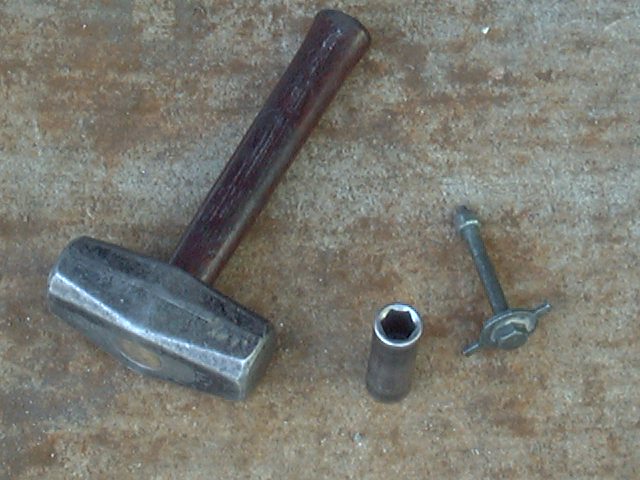
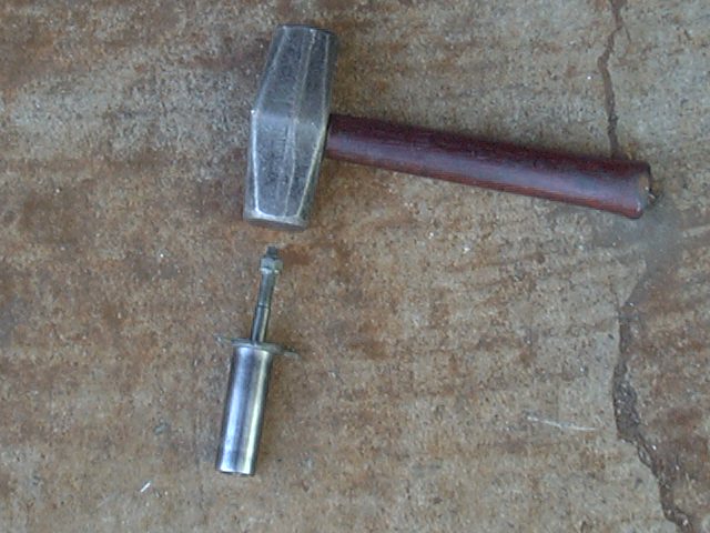
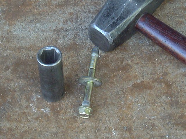
A hammer is useful to remove the stock "captive washers" for re-use. Some folks have had trouble with re-using the stock body washers as they are often a captive design where the washer is pressed onto the bolt at the factory. Its very easy to do with a socket and hammer:
 |
 |
 |
| A: Captive tabbed washer | B: Inserted in socket, hit with hammer | C: Washer pressed off bolt |
Here is a tabbed washer and standard head bolt. Use a socket that fits the head of the bolt (17mm in this case - A). Place socket on hard surface and strike the end of the bolt with the hammer (B). Note, pictured horizontally for ease of picture taking. One solid hit and the washer pops free (C)
 |
 |
 |
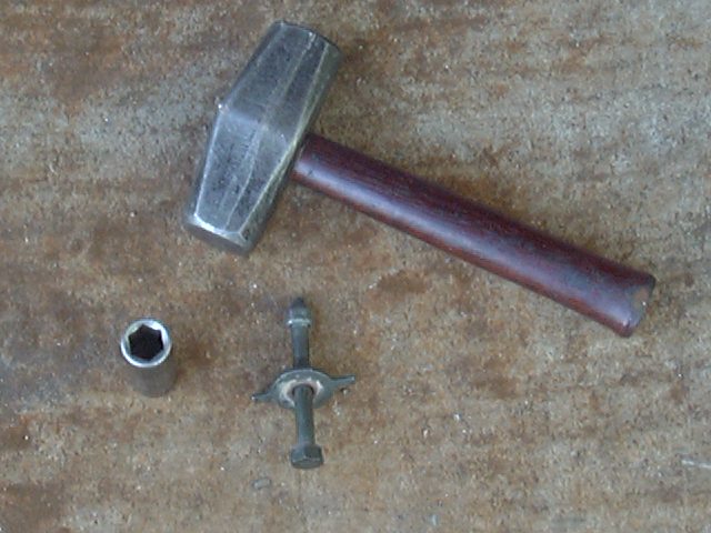
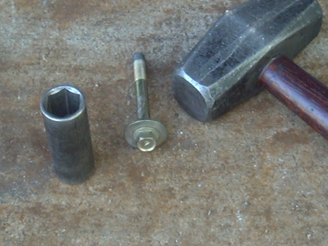
| D: Captive round washer, bolt has flanged head |
E: Inserted in larger socket, hit with hammer |
F: L-R: SAE flat washer factory washer and hardened washer |
Picture D shows a captive round washer and flange head bolt. Use a socket that fits the over the flanged head of the bolt (21mm in this case D). Place socket on hard surface and strike the end of the bolt with the hammer (E). The reason to re-use the factory washers is apparent in picture (F). Note the thickness of the stock washer (center) and its large diameter. This is very important as the size and thickness of that factory washer will prevent that body mount bolt from pulling through the floor, so DO NOT SKIP THIS IMPORTANT STEP, the life you save may be your own!
- You can use a deep well socket and a hammer, as shown above.
-
What if you don't have those tools?
- Use a short length of steel water pipe
- 1/2" (or suitable metric equivalent) trade diameter or larger should be fine
- Length is not terribly important as long as the head of the bolt fits inside and has enough room to push down the thickness of the washer
-
Don't have any short piece of pipe?
- Go the the hardware store and pick up a short threaded pipe nipple or coupler (see above for size information)
-
Don't want to buy any pipe?
- Then stick the bolt upside down between the jaws of a vise
-
Don't have a vise?
- Use two bricks or pieces of wood spaced wide enough for the head of the bolt to fit between but not the washer
-
No hammer?
- Try using a bottle jack from your vehicle, place the jack on the ground under the frame, place the socket on top with the bolt up against the frame and raise the jack; the weight of the vehicle will press the bolt out of the washer with ease
While a normal stamped flat washer is about the right diameter but is too thin and soft to span the hole in the floor of the body and will dish downwards under the load and fail. A hardened Grade 8 washer is probably strong enough for the load, but is too small to span the hole in the floor, so will pull through under load. So it is important to re-use the stock body mount bolt washers with the new body lift hardware. Those washers are specially designed by the factory to work in that application.
And you'll also be re-using some of the other original washers, like the ones at the bottom of the body/cab mount bushings. So, be sure to take note of how the factory bolts were set up and then grab any needed washers off the factory hardware to re-use with the body lift install. And, in certain cases, such as on pickup beds, where the factory washers are welded to or part of the factory bolts, new washers will be supplied with the body lift kit. In these kits, you may end up with extra washers, either the original ones or ones supplied in the kit.
If so inclined. you might want to toss the original hardware in a bag and label it. This way if you ever decide to remove the body lift, you'll have the original hardware to use to lower the body back to stock height. While you might not want to revert to stock, you might end up selling the truck and the potenial buyer may want to do that.
Also, when installing the new bolts with the body lift, if you find any where the nut bottoms out on the threaded section, you can always add a washer or two to take up any unthreaded bolt length. Certain vehicle models have some variability in bolt lengths and we try to supply a bolt that is long enough to fit the longest length we've encountered. But that may result in a bolt that is a bit too long for another vehicle. You can add those washers up under the head of the bolt and that way they'll be out of sight under the carpet or floor mats. You can always make the longer bolt work, but if it's too short, there's no way to lengthen it.
Speaking of re-using the original factory hardware, assuming you're lifting the vehicle from stock, consider saving the original hardware if it's in otherwise decent condition. Why? Maybe you decide to sell the vehicle some time later and the buyer doesn't want a lifted truck. With a set of stock length hardware, it's easy to revert the body to stock height. Or perhaps as the years go by and either your or a significant other maybe can't deal with climbing up into the truck. Or maybe to install something like a solid axle swap and now have tons of lift and no longer need the clearance of a body lift. I still have the original factory bolts (at least those which were still on the vehicle when new poly bushings were installed) from 25+ years ago.
And what if you chucked the original hardware? No worries, we can supply stock length hardware for many vehicles.
[Return to the top of this page]Safety First:
PLEASE READ all instructions all the way through BEFORE YOU START! Safety First! Before you undertake any suspension modifications, remember that such mods may change your vehicle's handling characteristics and stability. Raising your vehicle's center of gravity with extended shackles, body lifts, etc., may increase the likelihood of a rollover, especially at high speed or on uneven terrain. Hence, all 4Crawler Offroad products are designed and intended for off-road use only. It is entirely your responsibility to determine the fitness and suitability of this 4Crawler Offroad product for your application. 4Crawler Offroad will accept no responsibility for any unsafe condition, damage or personal injury arising from your use of this product. Your safety depends on it!Park vehicle, securely block wheels to prevent it from rolling. Since you'll be moving the body in relation to the frame, it is a good idea to disconnect the ground cable from the battery to avoid unexpected short circuits as well as inadvertently putting too much strain on the battery terminals if the cables pull tight during the installation. However, if you have a newer vehicle and/or newer radio with security codes, you may not want to do this unless you can get your radio security features reset, or better yet, invest in a memory saver backup battery that plugs into the cigarette lighter to maintain a small amount of power for memory circuits. If you plan on raising the stock front bumper, disconnect the wiring harness from the turn signals. On air bag equipped vehicles, sensors for that are usually in the frame behind the bumper brackets, so they should be unaffected by the lift.
The actual lifting process should go quite easy, the body is only a fraction of the weight of the vehicle. If the body seems to get hung up, don't force it, figure out what is hanging it up before proceeding. Also, you'll want to lift from close to the balance point of the body/bed. Where exactly that point is is not important. try to err to the rear and find a convenient lifting point near there. The reason for erring to the rear is that there are more attachment points up front that can cause problems if lifted too far.
- IMPORTANT!
- When lifting the body, be VERY careful not to force anything. The body should come up easily and if it doesn't, STOP and find out why. Check for hidden bolts on bumpers, trim, etc. Check for wires, hoses, and other mechanical parts that are holding things up. You want to raise one whole side if possible, rather than a corner at a time. Why? Its more likely to twist the body if lifting one corner only and you may go so far as to crack a window.
Now on to the lift...
[Return to the top of this page]Body Lift Removal:
While these instructions are mainly written around the installation of a body lift kit on a vehicle. They are equally appropriate to the removal of an already installed body lift to either revert to stock height or to install a lower height body lift. As the old saying goes, "removal is the inverse of installation". So just go to the section of these instructions that deals with the part of the vehicle you are working with and then basically follow them in reverse order. So you'll essentially be removing all the various brackets and spacers for things like bumpers, radiators, steering, etc. Then remove the body lift blocks themselves and installing stock length hardware all around. Then finally lower the body down to the frame and the body lift is gone. In cases of brackets, you;ll typically be unbolting those, saving any stock hardware, such as bolts that go into the frame, then re-use that stock hardware to re-attach whatever used to have a bracket to the frame.
Not all body lifts are the same. With our kits, all our brackets simply bolt onto or at most require drilling new holes in the existing brackets for things like bumpers. However, some kits supply new brackets for things like bumpers. With those, you have a few options. If whoever installed the kit kept the factory brackets, you can re-use those. If there are no original brackets, then you may be able to drill new holes in the lift brackets in order to adapt them to a lower height. A third option for brackets, is to pick up some OEM brackets at a junk yard. All you need to get is something from a similar generation vehicle to yours. You don't need the whole bumper, just the brackets that fit between the frame and the bumper. Car-Part.com has a handy tool to search junkyards for specific parts. Ebay is another option, as is your local Toyota Dealer parts counter.
Likewise, you'll be retaining the stock body mount bushings after removing the body lift blocks, unless you plan to replace those bushings with a poly urethane bushing kit. This part is up to you. It is always a good idea to inspect your existing body mount bushings prior to removing a body lift. If they are worn out, damaged, or even missing, now is the perfect time to replace them.
For pickup models, there are typically no "bed mount bushings", instead the bed just sits in directly on the frame brackets. Sometimes, there will be small rubber pieces that you can sit between the bed and frame. Or we also offer round poly urethane isolation discs that you can install between the bed and frame if you wish. The reason there are no bed mount bushings is because the bed of a pickup is intended to haul cargo and not people. You can imagine having a half ton of cargo in the bed, with it riding on tall rubber cushions, and having that swaying side to side as you drive down the road.
[Return to the top of this page]Body Mount Bushings:
Body mount bushings, whether the factory rubber pieces or the replacement polyurethane pieces are used to isolate the body of the vehicle from the frame. They are used whether the vehicle has a body lift or not. Whether only replacing the OEM bushings with poly or installing a body lift along with poly bushings, the procedure is basically the same as installing a body lift, as noted in the vehicle-specific sections below.
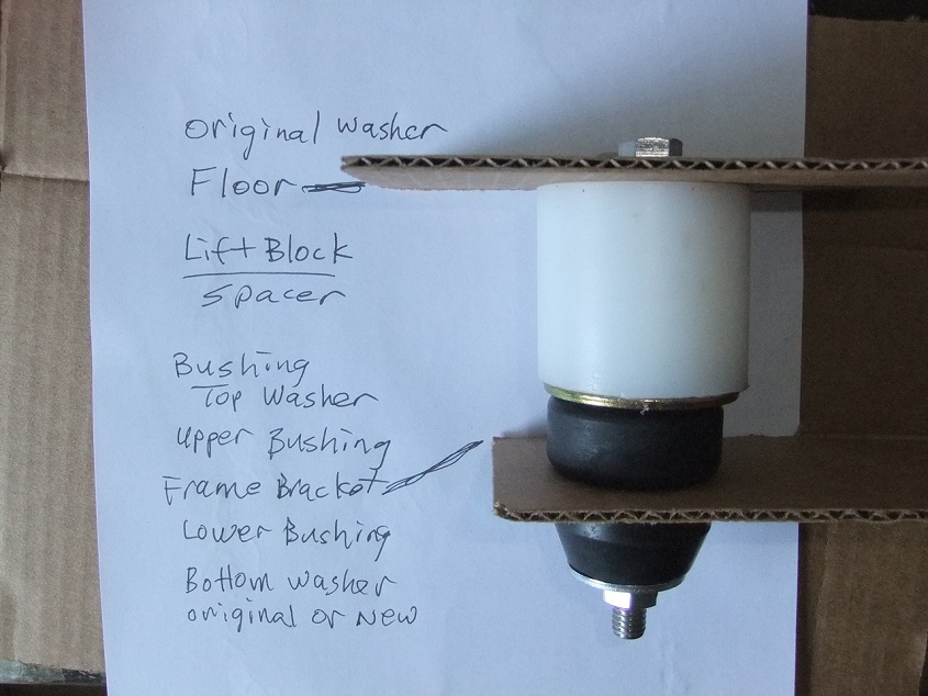
This is a generic diagram of the typical body mount bushing setup. This applies whether this is the OEM rubber or replacement poly bushings. The bushings themselves are typically composed of an upper and lower half bushing, a metal sleeve that fits inside and a top and bottom washer. The two washers serve to compress the bushing halves around the frame bracket in the middle and the sleeve sets the proper amount of compression before it bottoms out.

Here is a 2nd gen 4Runner showing the additional spacers that are suppled with some bushing kits to make up for height differences between the OEM rubber bushings and the polyurethane bushings. Notice how the 4th and 5th bushings have the added spacers that sit on top of the upper bushing and the top washer like a body lift block would. If the bushings are ordered with a body lift, the height of the spacer is added to the height of the lift block:
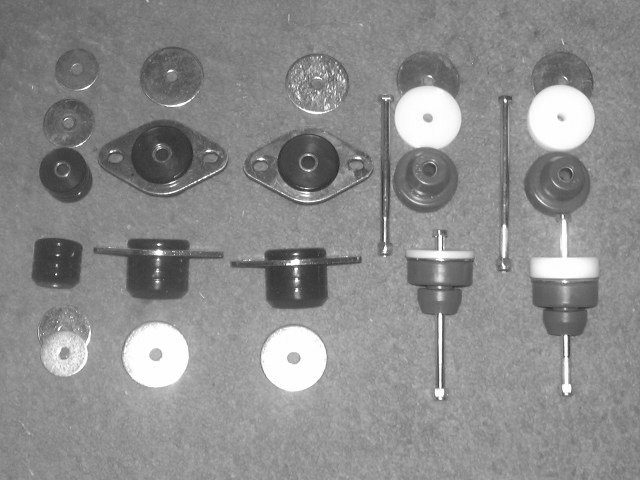
On the Toyota pickup, Tacoma and 4Runner kits, there are typically two smaller bushings for the front under the radiator. Then 4 or 8 larger bushings for the remainder of the cab/body. Pickup beds typically have no bushings or at most a scrap of rubber or plastic. You can eliminate or re-use the original rubber or if you want to replace that material, use a scrap of inner tube rubber or some plastic milk bottle cut into a disc with a hole in the center. Or we also have available round polyurethane washers (item: Pb), they can be fit in between the bed and frame to replace the original rubber pieces.
Unlike with poly suspension bushings, therre's no need to apply any lubrication to the body mount bushings to prevent squeaking. As there's no relative motion of the body across the body mount bushings, squeaks should not be an issue, so no need for grease.
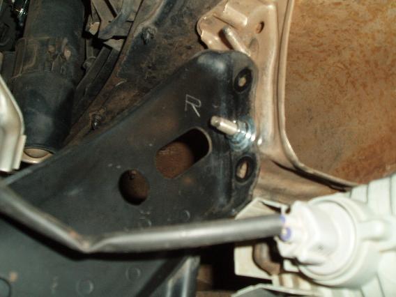
Some of our bushing kits include UHMW spacers to make up the height differences between the OEM and poly bushing pieces. In case of bushings ordered with body lifts, the body lift blocks will be made with the spacer height built in, so will therefore be of differing heights. In these cases, the components will be labeled with recommended locations using the following letters, F =Front, A = A-pillar, B = B-pillar, C = C-pillar, R = Rear.
Think of these spacers (or additional block heights) as 0" body lift spacers. They are what get you back to stock height when combined with the poly bushing. For example, if your OEM rubber bushing is 1" tall, and the poly bushing is 3/4" tall, you need a 1/4" tall spacer to make the height of the poly bushing match that of the OEM rubber bushing. To make this more clear, line up the poly bushing + spacer next to the OEM bushing upper half and compare the heights. So in this example, 3/4" + 1/4" equals the 1" height of the OEM bushing. In fact we recommend comparing the OEM bushing removed from each location with the poly bushing + spacer replacing it and make sure the heights are similar. There may be slight differences when comparing compressed vs. uncompressed heights due to rubber and poly having different amount of deformation under compression, but they should be close. If you find a better mix of bushings and spacers that better match your original bushings, by all means go for that instead of our generic labeling. Every once in a while, a certain model vehicle will be made differently than normal. We run into this a few times a year.
In short, with the poly bushing + spacer, just install the spacer between the top washer of the poly bushing and the body before installing the bolt and lowering the body back down. What you are looking for is that the body, when lowered down, sits fairly evenly on all the body mount bushings (and spacers). If it doesn't no harm in moving spacers and bushings around for a better fit. You might have one of those vehicles, as noted above, that are made a bit differently than typical for your model year.
Some customers have ordered a 2nd heavy duty washer (HDw) kit so they have additional washers to use as spacers on top of poly bushings in situations where the body may not sit flat on the new bushings. This usually happens due to frame or body sagging over the decades. The washers are approx. 3mm thick and you can place them between the large top washer and the underside of the body to even out the bushing heights. This is more noticeable with the poly bushings because they don't expand as much as the original rubber bushings did. The rubber bushings will appear to fill in those gaps because the taller ones compress first until all the bushings make contact. The poly is firmer than the rubber and doesn't compress as much.
Note: On some vehicles, if re-using the stock body mount bolts with the new poly urethane bushings, you may run into situations where the threaded portion of the original bolt is too long for the typically shorter poly bushing. Some OEM rubber bushings are very tall, especially below the frame bracket. The poly bushings are often shorter, overall, that the original rubber bushings. If you run into a "too long" bolt, several options are possible. First, you can stack some additional washers on the end of the bolt before installing the nut, or if you want them out of sight, you might be able to put the washers under the head of the bolt that's hidden under the floor of the vehicle. Second option is to try swapping bolts with another body mount location, as bolts in different locations can be different lengths and/or have differing amounts of thread. Third option is to pick up shorter bolts at a local hardware store. Good idea to take the bolt with you, with the desired length marked, and then find a suitable replacement and use that instead. Or fourth, we offer full replacement bolt kits for the poly bushings that are sized to fit the poly bushings.
For pickup kits, we also offer polyurethane bed isolation washers (Pb). These washers are meant to replace the factory rubber pieces that sit between the bed and frame brackets. In manyu cases, those old pieces of rubber have cracked and disintegrated with time. The new polyurethane washers replace that old rubber to cushion the metal on metal connection. These are good to install if removing a body lift, or if installing a body lift with metal lift blocks, like our 1" aluminum lift blocks or they can be used with all out UHMW lift blocks. Note tha the UHMW lift blocks will serve a similar function as they eliminate the metal to metal connection.
[Return to the top of this page]4Runner (and other full bodied vehicles):
Check your kit to ensure all parts are present. You should have:
- Lift blocks, 10 for 4Runner (1st-3rd gen or 8 for 4th gen vehicles), 12 for FJ-60, 10 for FJ80, 8-12 for Montero, 8 for Sportage
-
Longer bolts, Grade 5 or better (if required) and lock nuts
- You'll be re-using the stock body mount washers, some additional washers may be included in the kit
- Optionally, you may have additional brackets and hardware for bumpers, radiator, steering, etc.
Some of the body mount bolt heads are located beneath the carpet, so remove the trim along the door that holds the carpet in place. Remove the plastic covers over the body mount locations, including the pair of mounts under the rear seat cushions. Loosen the nuts on all body mount bolts, remove the nuts from the side you will lift first, leave the nuts in-place on the opposite side (to keep the body from shifting). You may want to loosen clamps on the steering shaft too. And finally remove the front bumper for better access to the front body mounts. Usually there are a pair of bolts attaching the bumper to the frame, as well there are often several smaller bolts attaching the ends of the bumper to the fenders. Disconnect any light connectors and pull the bumper off and set it aside.
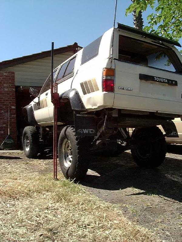
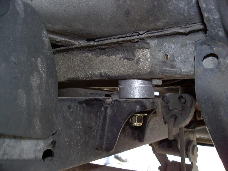
One option is to use a HiLift jack in the rear wheel well (see picture,above - with a length of 2x4 along the top of the fender well). It is a bit behind the natural balance point, the rear end will be lifted a bit higher than the front end. A floor jack placed under the body with sufficient wooden blocking works just as well
- Note how the base of the HiLift is tucked under the tire and the tires are securely blocked
- It is also a good idea to wrap a towel around the top of the jack to prevent it from scratching the paint if it gets too close to the body
Lift the body slowly and evenly, checking frequently for binding and connections that may be hanging up.
- Note:
- Depending on your body and suspension setup, you may find you need to raise the body a considerable distance before the suspension unloads (due to removing the weight of the body from it) and the body finally separates from the frame. If you find you are running out of jack travel and can't lift the body high enough, consider using a chain or strap around the axle and frame to keep the suspension from unloading so far.
You'll need to raise the body until there is approx 1-1/2" of clearance between the body and body mount bushings to allow installation of the lift blocks. You may want to check the clearance of the fan and shroud on the radiator. If it looks tight, you can remove the lower part of the shroud (see Radiator Drop Bracket instructions) or unbolt the shroud altogether. Some vehicles may have bumper components that override the body (such as the Montero rear bumper or Toyotas with Smitty Bilt tube bumpers), so it may be necessary to loosen and/or remove the bumper to raise the body.
Hint: If you are planning to install polyurethane bushings, now would be a good time to remove the stock ones and install the new ones.
Proceed down the body, removing the stock bolt. If the stock bolt has a "captive" tabbed washer, this can be removed and re-used on the new, longer bolts:
- Place the bolt, head-down between two blocks to support the washer or use a deep well socket big enough to fit the head of the body mount bolt in and drive the bolt out of the washer with a hammer or press
- Put a nut on the end of the bolt and tap it firmly with a hammer to drive the bolt out of the washer
-
Install the new, longer bolt, and reverse the procedure, driving the
bolt shank into the knurled washer until its fully seated
- In the picture below, you can see the tabbed washer removed from the stock bolt and pressed onto the new bolt
- Note that on the standard size hardware, the stock washer will simply slide on the bolt and you'll need to use a wrench or pair of vise grips on the head of the bolt to keep it from turning. Alternately, you can tack weld the head of the bolt to the washer if you want to retain the "captive bolt" feature. Or with the oversize hardware option, you can get the old washer pressed onto the new bolt with a good tight fit.
- The tabbed washer is used to prevent the bolt from turning when you tighten in, a wrench on top does the same thing and it is an extra strong washer to span the large hole in the floor
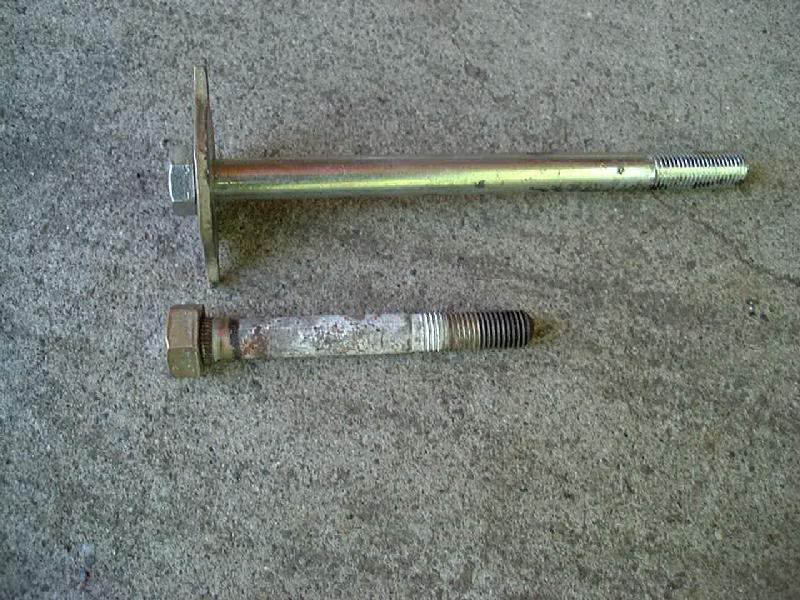
Many vehicles have different length bolts for the various body mount locations. One tip is to lay each stock bolt adjacent to its location on the vehicle. Then match up the new, longer bolts with the stock ones to ensure that the correct length bolt is used. Also, it is often the case that some of the stock bolts can be re-used in another location. It is perfectly fine to do this if its easier. In general, here are some bolt length layouts for common vehicles:
- 1st gen 4Runners have all the same length bolts
- 2nd gen 4Runners have the shorter bolts in front, longer bolts to the rear and the middle length bolts in the middle
- 3rd gen 4Runners have the longest bolts up front, shortest to the rear and middle length in the middle
- 4th gen 4Runners, have the short bolts up front and the longer bolts in the middle and rear
- Monteros have equal length bolts in all locations or on some models have the inch longer bolts at the very rear
- IMPORTANT:
- And take note that there may be different bolt diameters and thread pitches with the supplied hardware. Be sure and keep the nut with the bolt it came on. Nuts are supplied pre-threaded on the bolts to ensure that there is no problem with the nut and both threads fitting. If you find you can't spin a nut on a bolt easily, remove it for inspection and correct any problem before trying to force it on, which can result in cross threading or stripped threads.
The front body/radiator mounts (pictured below on the left side) are typically smaller than the other body mounts (pictured below on the right side):
Early models:

Later Models: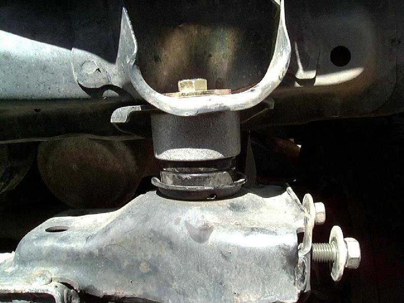

Slide a lift block in place, drop the new bolt down through the body, block, washer, upper bushing (and sleeve) and body mount bracket. Once all the blocks and bolts are in on one side, slowly lower the body, checking again to ensure everything is lined up properly. Then lower the body to compress the bushings. Finally, install the lower bushings (1st gen only) , any washers (either stock or new ones from your poly mount kit) and the new nylock nut. You can snug up the huts a bit, but don't make torque them yet. In the pictures, below, you can see examples of one- and two-piece bushings with the lift blocks installed:
2-pc. bushing: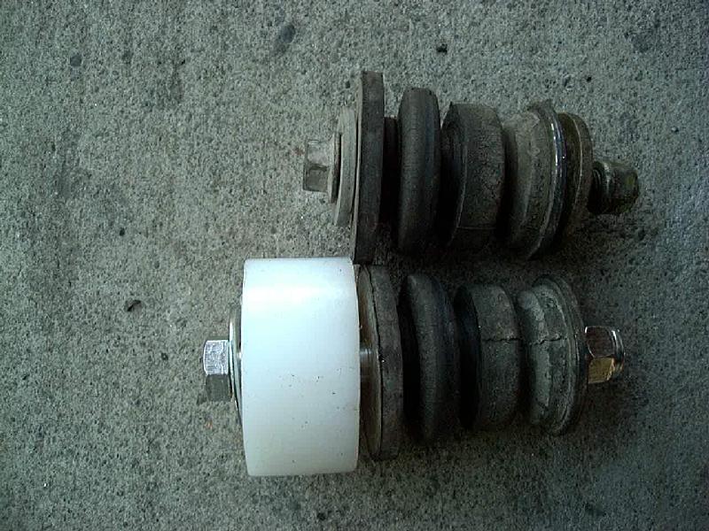
- Notes:
- It is important to use a washer above and below the body mount bushings as shown in the "2 piece" pictures above. This washer is usually bonded to the stock rubber bushings if you are reusing them, or should be included with your polyurethane body mount bushings. The washers are there to contact the metal bushing inside the poly bushings when the bolt is tightened. The metal bushing ensure the poly bushings are compressed properly to secure the cab to the frame, yet allow for some degree of compliance.
- For 2nd gen 4Runners installing replacement poly urethane body mount bushings:
-
The new poly bushings are installed in place of the OEM rubber parts
- Labeled as follows: F=Front, A=A-pillar, B=B-pillar, C=C-pillar, R=Rear
- For more information, see: /4x4/ForSale/BodyLiftKit.shtml#PolyBushings
- Labeled as follows: F=Front, A=A-pillar, B=B-pillar, C=C-pillar, R=Rear
Now reset your jack to the other side and repeat the above steps. Refer to the Torque Specification section for details on finishing the body lift.
[Return to the top of this page]Pickup and Tacoma:
Check your kit to ensure all parts are present. You should have, at a minimum:
-
14 or 12 lift blocks
- Certain versions may have different sized holes in the cab and bed blocks, designated by "C" for cab and "B" for bed.
-
Cab and bed bolts, nuts and assorted washers
- You'll be re-using the stock body mount washers, some additional washers may be included in the kit
- On 1st/2nd gen pickups, the 6 cab bolts are all the same length and of a smaller diameter than the 8 bed mount bolts
- On 3rd gen pickups, the front most cab bolts are shorter than the other 4, and the 8 cab mount bolts are the same length
- On Tacoma pickups, the longer cab bolts fit up front, the short ones to the rear. Some models may have middle length bolts in the middle of the cab. The 6 bed mount bolts are all the same length.
- Optionally, you may have additional bracket and hardware for bumpers, radiator, steering, etc.
- IMPORTANT:
- And take note that there may be different bolt diameters and thread pitches with the supplied hardware. Be sure and keep the nut with the bolt it came on. Nuts are supplied pre-threaded on the bolts to ensure that there is no problem with the nut and both threads fitting. If you find you can't spin a nut on a bolt easily, remove it for inspection and correct any problem before trying to force it on, which can result in cross threading or stripped threads.
Doing a body lift on a pickup is actually two separate tasks with an extra step or two at the end. First, you lift the cab, then the bed, then align the bed to the cab. It seems to be easier to align the bed to the cab if they are at the same height, since the body contours line up properly, but you can do it either way, it really makes no difference.
Refer to the 4Runner section of the instructions for instructions on raising the body. The rear cab mount bolt heads are located beneath the carpet, so, remove the trim along the door that holds the carpet in place. Remove the plastic covers over the cab mount locations. Loosen the nuts on all 6 cab mount bolts, remove the nuts from the 3 on the side you will lift first, leave the nuts in-place on the opposite side (to keep the body from shifting). And finally remove the front bumper for better access to the front body mounts. Usually there are a pair of bolts attaching the bumper to the frame, as well there are often several smaller bolts attaching the ends of the bumper to the fenders. Disconnect any light connectors and pull the bumper off and set it aside. Also, on the Tacoma, you should unscrew the gas tank filler cap in case the filler tube pulls it down through the plate behind the filler door while lifting.
A floor jack with appropriate blocking to raise the body from about the front seat area makes a good balance point. Lift the body slowly and evenly, checking frequently for binding and connections that may be hanging up. You'll need to raise the body until there is approx 1/2"- 1" more than the body lift height of clearance between the cab and cab mount bushing to allow installation of the lift blocks.
Now, you are ready to start lifting the bed. Loosen the nuts on all 6 or 8 bed retaining bolts, remove the nuts from the side you will lift first, leave the nuts in-place on the opposite side (to keep the bed from shifting).
-
On the , take care when removing
the stock nuts from the rear-most bolts, as they will need to be
re-used.
- Also on the Tacoma, the forward 4 bed bolts are screwed into captive nuts in the bed rail. Take care removing these bolts as it is difficult to replace the nuts if they are damaged.
- You may want to apply some anti-seize compound (or grease) to those bolt threads before installing the new hardware in case you ever need to remove the bed in the future. That will help to ensure the bolts are easy to remove if needed.
Notice the bed mounts lack the compliant bushings found on the cab. Also, note that the stock bolts are designed to be inserted in the channel above the mount and dropped down through the hole. The hardware kit for the pickup body lift kit includes nuts with welded-on tabs, similar to the stock bolts, to keep the bolts (or nuts) from turning, making for an easier installation process. But due to the additional length of the body lift hardware, the nuts with the tabs are inserted in the channel under the bed and the bolts run up from below. A HiLift jack with a piece of 2x4 blocking under the rear wheel well made a good lifting point, otherwise a floor jack and sufficient blocking to reach the bed floor will work. Lift the bed slowly and evenly, checking frequently for binding and connections that may be hanging up. You'll need to raise the bed until there is approx. 1/2" more clearance between the body/bed and body mount bushing than the height of the lift being installed to allow room for installation of the lift blocks.
Proceed down the bed, removing the stock bolt and square rubber washer, install a lift block and then the new bolt with welded on tab, it may take a few tries at the proper orientation to get it into the hole in the bed. The bolts in the kit are designed to be just barely long enough for the 1" lift, yet short enough to fit into the tight space under the bed. If you find it "impossible" to get the bolt in from above, don't sweat it, it'll work just as well from underneath, with the nut on top. Once all the blocks and bolts are in on one side, slowly lower the bed, checking again to ensure everything is lined up properly. Finally, install a washer and the new nylock nut. You can snug up the nuts a bit, but don't make torque them yet. Now reset your jack to the other side and repeat the above steps.
- Note, you do not need to re-use the stock rubber bed isolation washers. Their main purpose is to separate the bed from the frame to prevent metal to metal contact. The UHMW-PE lift blocks serve the same purpose. If using the aluminum lift blocks, you can either re-use the rubber washer or add a washer cut from an old milk jug or just use the aluminum as-is. All will work, just depends on your preferences.
- On pickup lifts over 1" tall, its not possible to insert the bed bolts from the top like the factory bolts are. Therefore, the bolts go in from below and the nuts go on top. The nuts have tabs welded to them to prevent them from turning while tightening the bolts down. There is very little space to fit a wrench in to hold the nuts, so these tabs are a real time saver, that 4Crawler Offroad duplicated from the factory fasteners. Because the tabs are welded in place, it is not possible to use nylon insert lock nuts, so it might be a good idea to use some thread locking compound on the bolt threads.
- On the Tacoma pickups, there are only 6 bed bolts on most models. Also, the bolts install upwards into captive nuts and are varying lengths. Be sure to use the proper length longer bolt for each location. You will be re-using the existing nuts and washers, so keep track of those parts.
- If installing Bed Spacers, do so now, before lowering the bed down and tightening the mounting bolts.
Then, before you torque down the bed bolts, make sure the bed is properly aligned with the body. If it has shifted to one side, you can lift and reposition it by hand to get it lined up. Once it is aligned, refer to the Torque Specification section for details on finishing the body lift.
[Return to the top of this page]Steering Shaft Adjustments:
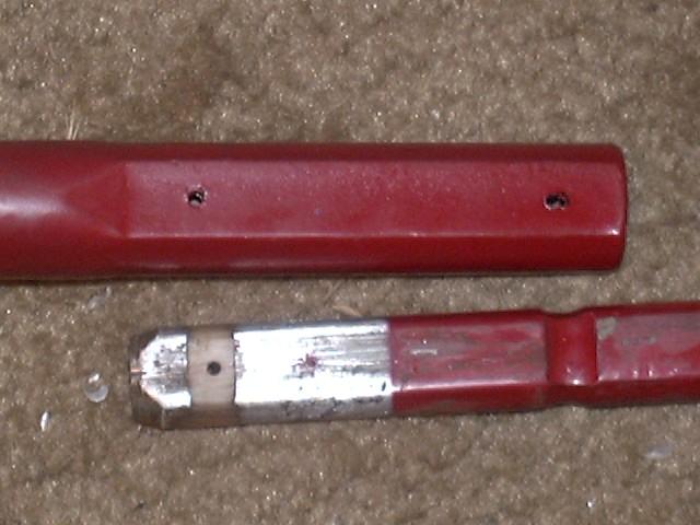
The top clamp (see picture A below) on the steering shaft should be loosened prior to lift the body off the frame. On some models, it is the bottom clamp near the steering box that has this slip yoke. It seems that Toyota builds the steering shaft with one clamp that is basically fixed and the other clamp that has splines that allow for moving in and out. So find the clamp that looks like it will move and try that, if it does not move, try the other one. This will allow the shaft to pull out of the clamp to accommodate the lift. You can remove the bolt from the clamp and see if the bolt actually is clear of the shaft or if it passes through a groove in the shaft. If there is a groove that the bolt fits into, leave the bolt out, otherwise it can be re-installed loosely. If the shaft does have a groove, you may need to make a new groove for the bolt to fit into after the lift if the groove doesn't exactly =line up with the bolt afterwards. This can be done with a drill, using a bit that just fits inside the hole (around 8mm or 5/16"-11/32"), using the hole in the clamp to guide the bit.
Other options for extending the steering shaft is to remove the long, straight section. Then cut this section in two and use a length of steel tubing that the shaft just fits inside, typically 3/4" or 19mm ID tubing, to sleeve the joint. A section 3/4" black steel gas pipe is one option, it's inexpensive and available at most hardware store. Ideally some rosette welds through the sleeve to the shaft below plus welding at both ends of the sleeve by a competent welder should make a good extension. You could also drill some holes in the tubing/shaft and run some bolts through along with welding the sleeve to the shaft.
Vehicle Specific Notes
- Toyota Recirculating Ball Steering Adjustments
- Toyota Rack and Pinion Steering Adjustments
- 4th Generation 4Runner, FJ Cruiser and 2005+ Tacoma pickup Steering Adjustments
- Steering shaft extension photo album: Google Photos with high res. phtots and descriptions
- General Steering Adjustments and Checks
Toyota Recirculating Ball Steering:
On the '83 and earlier Toyota pickups, the steering shaft often has an actual slip yoke segment and that will pull out to accommodate most body lifts without needing to do anything special. For later model pickups and 4Runners, depending on the amount of lift, it may be necessary to adjust the steering shaft to accommodate the body lift. It is a good idea to loosen the steering shaft clamp (lower left image) to allow it to slide out as you lift the vehicle. Be sure to mark the shaft and clamp so that you can line both up if they do pull apart during the lift. If you anticipate needing to extend the steering shaft, one option is to drill out the plastic "pins" prior to lifting the body, then allow the lifting process to pull out the steering shaft halves. For Toyota vehicles with rack and pinion steering and vertical steering shaft, see the following section for details on steering shaft adjustments. The section below describes adjustments needed for vehicles with recirculating ball steering boxes, that are mounted to the outside of the frame in front of the front axle.
You can see the black mark on made on the steering shaft splines (image A below) before doing a 2" lift and you can see how far the splines pulled out, just a bit over 1/2". If the clamp and spline are rusty, you can spray them down with penetrating oil and even use a screwdriver or chisel to open the clamp up to free it. Note that on some vehicles, that upper clamp may be under a plastic cover or it may be behind the firewall, accessible from under the dash inside the cab. There is also a clamp at the bottom end of the steering shaft, this one is usually not adjustable as it will typically have a groove through which the clamp bolt fits. This means the clamp bolt can only be installed with the shaft inserted until the groove lines up with the bolt hole. In case the upper clamp is stuck on the shaft, you can usually loosen the clamp bolts and then use a hammer to tap the bottom end of the shaft near the rag joint down and alternately turn the steering wheel back and forth (with the tires on the ground) to help break the shaft free from the clamp.
 |
 |
| A. Upper Splined Clamp | B. Rag Joint |
In the upper right image, you can see the rag joint that is usually at the bottom end of the steering shaft, at the steering box. It uses a rubber center section and you want the rubber to not be under any stress. If the rubber section takes on a wavy look (/\/\) you need to loosen the clamp and let the spline slip out to relieve the stress. If the spline slips out too far, with less than 1/2" of so of spline engagement, then it will be necessary to make some modifications.
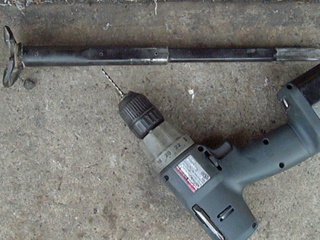
For trucks with conventional steering boxes and a two-piece (collapsible) steering shaft at an angle, you can do the following:
 |
 |
| Drill out plastic pins | Shaft is now free to move |
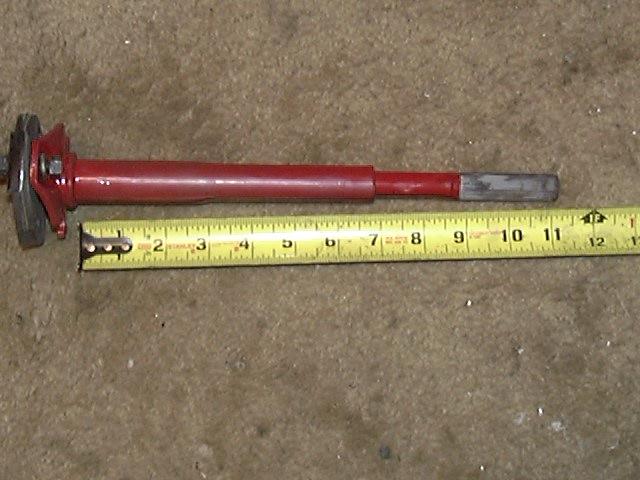 |
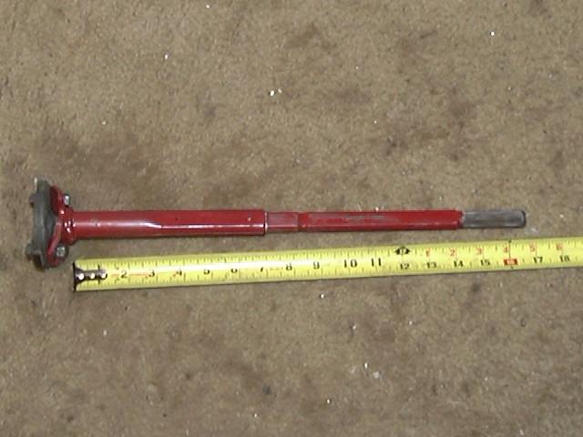 |
| Collapsed to 11" | Extended to 17" |
- Mark the splines on the steering shaft in engine compartment at steering box and steering column
-
Remove the shaft
- Loosen the top and bottom clamps
- Or see above note and leave the shaft in place, drill out the "pins" and let the body lift process pull the halves apart
- The "pins" are not really pins in a sense that they are inserted through the shaft, rather the way these shafts are assembled at the factory is that liquid plastic is injected between the two shaft halves through the holes to hold the shaft at a given length. You can see the remaining plastic in the groove in the inner shaft in the upper right hand photo above. This technique holds the shaft halves together yet still allows them to collapse in the event of a heavy front end collision.
-
Mark a line on the rag joint to the shaft itself, then remove the rag
joint assembly
- Remove the nuts on the long studs, then tap them out with a hammer
- Then you can remove the shorter bolts
- Remove rubber cap from end of shaft
-
Drill out both shaft locating pins on a drill press with a 1/8"
drill bit
- The pins do not go all the way through the shaft
- Scribe a line on the inner shaft where it slides into the outer shaft
-
Extend the shaft from its original position an amount equal to the
dimension noted in the first step
- Sometimes it helps to first fully compress the shaft first to loosen it up a little. This is easily done with a rubber mallet, dead blow hammer or regular hammer with a block of wood to protect the end of the shaft from the blows.
- Then to extend the shaft, find a rod to fit inside the hole at the base of the shaft and holding the outer part of the shaft, drive the inner part out to extend it.
- You might find repeating the compress/extend cycle a few times will let the shaft extend easier. I found on my '85 shaft, if I pulled it all the way apart and then clean up any burrs, loose plastic and then greasing the shaft lets is slide in and out by hand. This makes for easier installation and removal.
-
Optionally, you may reinstall the pins following these steps:
- Drill a new 1/8" hole approximately 3/8" up from the bottom of the inner shaft
- Using the original upper hole as a guide, drill out the upper hole to 1/8"
- Install two 1/8" roll pins (not supplied in kit), then grind roll pins flush with shaft
Once all the modifications to the steering shaft have been completed, torque the fasteners to the recommended values, the upper steering clamp is 27 ft.lb. And be sure to check all the fasteners after a few hundred miles of driving. If you do remove the shaft to make these modifications, be sure to check the lower u-joint. You may find the u-joint bearings are tight. If so they can be disassembled to clean and re-grease the needle bearings, or new u-joint parts are available from the vehicle mfg.
Note:
4Crawler Offroad's test vehicle has been running a steering shaft without pins for many years. When a crossover steering kit was installed, the shop must have drilled out the pins when they swapped steering boxes. Once clamped in place the shaft can't move, it is clamped at the top and clamped at the bottom. When the steering shaft was pulled it out to document the drilling process and guess what, no pins. But if they were there, drill them out, plastic pin in a metal hole. Once free, the shaft should collapse to 11" and extend to over 17" (this is a safety feature built into the component in case of a front end crash). Installation is now a lot easier, collapse the shaft, clamp the steering box end, extend it out and into the upper clamp (making sure the alignment marks you made are lined up) and its done.
Some trucks may not have the collapsible steering shaft. You should be able to examine the steering shaft in your truck and see if its the two-piece design (as pictured above) or if its all one solid piece from end to end. You may also find there is another splined coupling inside the cab of the vehicle, near the firewall that has some adjustment as well. If so, you'll need to install an extension on the rag joint at the base of the shaft to lengthen the shaft if it will be pulled too far out of the upper clamp. Follow the instructions below...[Return to the top of this page]
Rack and Pinion Steering Adjustments:
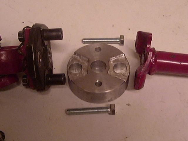
For trucks with rack and pinion steering (and vertical steering shafts or on trucks with 1-piece shafts and recirculating ball steering boxes) you will not be able to extend the driveshaft as shown above. Since the shaft is vertical, there is no need to make it collapsible for safety reasons, so instead it is a fixed length. If the shaft is only a fraction of an inch too short, you can add a few washers to the retaining bolts to lift the steering shaft off the rag joint. You probably don't want to go past the point that the large studs on the base of the rag joint won't engage the stops on the top of the rag joint. These stops are another safety feature that help limit the deflection of the rubber rag joint. If you need to extend the shaft 1" or more, you'll need to install a steering shaft extension; see image lower left:
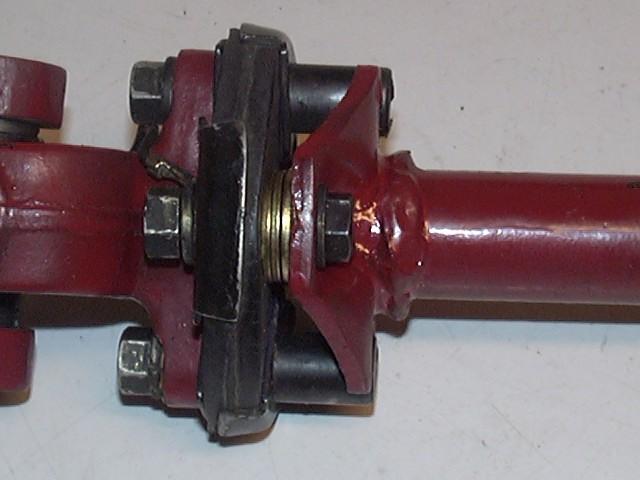 |
 |
 |
| Small extension w/ washers | Rag joint disassembled | Steering shaft extension installed |
An optional steering shaft extension is available (image above center). To install it, first secure the steering wheel to prevent it from turning on it's own, then remove the 2 short bolts (8x25mm) that attach the upper part of the steering shaft to the rag joint. The other studs (with the large round heads) are pressed into the rag joint and attach it to the lower part of the steering shaft. The rag joint itself is made of rubber and it it designed to flex back and forth to absorb road vibrations transmitted up the steering linkage and prevent them traveling up the steering shaft to the steering wheel. The spacer is installed over the stop bolts on the rag joint and includes longer bolts to attach it to the steering shaft (image above right). This extension allows for rag joint flex to absorb steering jolts, yet prevents overextending the rag joint like the stock arrangement.
Notes:
-
In the above photos, the steering shaft is shown removed from the
vehicle.
- This was done to allow clear photos to be taken.
- It is possible to install the extension with the steering shaft in place in the vehicle.
-
The extension is designed such that the large holes fit over the big
studs sticking out of the rag joint, once the upper part of the shaft
is disconnected.
- In very rare occasions, the steering shaft may have an extended center pin that projects through the rag joint. If your shaft has such a pin, you'll need to drill a clearance hole in the steering extension for that pin. You can use the existing pilot hole in the spacer to locate the hole.
- If you know ahead of time that you have such a pin on your rag joint, let us know the approx. diameter and length of the pin and we can pre-drill your steering extension to accommodate the pin.
- Then the supplied (longer) bolts fit through the small holes in the upper shaft, the spacer and the rag joint to tie it all back together.
- If needed, you may have to slide the steering shaft in or out of the upper clamp to fine tune the length to fit everything back in place with the spacer, this is normal.
-
On some vehicles, you may find that installing the extension makes some
part of the steering shaft to make contact with some part of the
chassis while steering.
- If this happens, it is typically a simple matter to find the point of rubbing and file or grind away the contacting material or bend back any contacting sheet metal as needed.
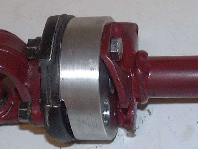
- Once installed, torque the longer bolts to factory specifications, usually 15-20 ft.lbs. Photo below is typical of rack and pinion steering shaft extensions (Tacoma and 3rd Gen 4Runner).
- Photo album with additional photos and information on the various steering extension options
4th Generation 4Runner, FJ Cruiser and 2005+ Tacoma pickup Steering Adjustments:
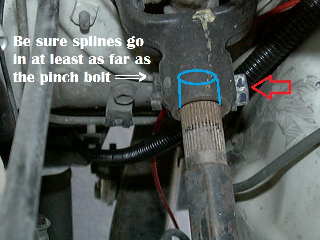
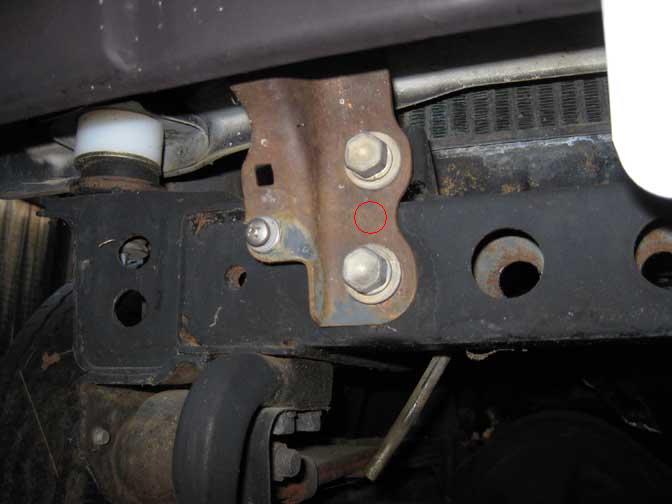
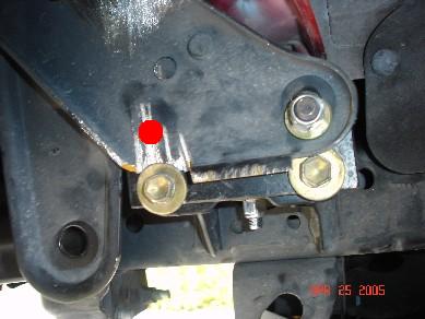
On the 4th generation 4Runners, FJ Cruiser and 2005+ Tacoma pickup models, take extra care to check that there is no residual stress in the steering shaft.
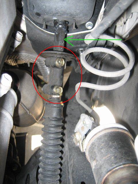
First secure the steering wheel to prevent it from turning freely. Then loosen the clamp with the two bolts (shown in the picture above - circled in red) between the intermediate and lower steering shafts and make sure that it has fully extended in order that it not be under any stress. If you find it hard to slide the shafts out of the clamp. turn the steering wheel so the gap in the clamp faces upward and then insert a flat screw driver blade or similar tool into the gap and pry it open a bit. Also, spray on a good penetrating oil to help loosen up the parts.
You can extend the two shaft ends to the point the ends are about in line with the center of the clamp bolts and still have adequate clamping force. There is a rubber rag joint on this model, but it is only visible from inside the cab, beneath a plastic cover where the shaft penetrates the firewall. You can remove that cover to see if the rubber segments in the rag joint have been stretched. If they are not sitting flat, or with the clamp loosened, you should be able to slightly move the shaft at the clamp. It would probably be a good idea to recheck the steering shaft clamp after driving a while to see if it'll slip out any farther once everything has settled into place. You don't want to leave any residual stress in the steering shaft after the lift is installed. Also. you want to pull the splines all the way out (visible coming out of the round housing in the photo above - indicated by the green arrow), as there needs to be some in and out travel there to account for body/frame flexing in uneven terrain. So, that is why you need to slide the shafts out of the ends of the bolted coupler as far as possible.
You should feel no binding in the steering, if you do this means you have not adjusted the steering shaft properly. If this is observed, usually at lift heights over 1", you may need to install an extension for the steering shaft as documented in this separate web page.
[Return to the top of this page]General Steering Adjustments and Checks:
If you notice a tightness or stiffness in the steering after installation, its likely the rag joint is under a bit of strain. Often there is a plastic cover over the rag joint (located at the base of the steering shaft), you can pull it up to examine the rag joint area. If the rubber is not laying flat, its likely under tension. To correct this, loosen the upper clamp and turn the steering lock to lock a few times, tapping on the clamp if its stuck, to release the tension. After the steering works free, be sure to tighten the clamp bolt to factory specs (about 19 ft.lbs.). It is a good idea to check the steering clamps and extension bolts for tightness after a few hundred miles of driving.
Also, there is usually a plate on the firewall where the steering shaft passes through. Its usually accessible from the driver's foot well area. Due to the lift, the angle on the shaft will become a bit steeper and the plate may need to be adjusted lower to line up the hole with the shaft if its rubbing. You may also find that the shaft may be rubbing on various heat shields or brackets around the engine or even on the inner lip of the wheel well, if so, they may be bent slightly to clear.
[Return to the top of this page]Bumper Relocation:
Various vehicles have front and/or rear bumpers that may need relocation with the body lift. Below are links to the various bumper applications:
[Return to the top of this page]Front Bumper Relocation:
If you currently have the stock front bumper and intend to retain it after the body lift, it may be lifted an amount equal to the body lift to cover up the gap left when the body was raised. Some body styles require the bumper be lifted in order to reinstall it. If you ordered the optional bumper lift brackets, you can either weld them to the stock bumper bracket or bolt them on with the supplied hardware. This is one ask where an extra set of hands (i.e. a helper) can come in handy. One person to hold the bumper up in place and a second person to install the mounting bolts. The style of the bumper bracket varies by vehicle:
- 1st Generation 4Runner and Pickup
- 2nd Generation 4Runner and Pickup
- 3rd Generation 4Runner and Tacoma
- 4th Generation 4Runner and FJ Cruiser and '05+ Tacoma pickup
1st Generation (Pickup '79-'88; 4Runner '84-'89) bracket:
| [image soon] |  |
 |
| A: Front Bumper brkts. | B: Brkt. Installed | C: Stock brkt. mods. |
Pictured above are some pictures of some typical '84-'88/'89 front bumper relocation brackets (kit item: FB). There are many variations of this generation of front bumper lift brackets owing to the two different bolt hole spacings (2"and 3") Toyota used over that period of time as well as the 4 different body lift kit heights (1", 1.5", 2" and 3"). So instead of trying to show all possible configurations, we'll show one and point out differences.
Image A, above, shows a typical front bumper lift bracket kit (item: FB), in this case a 1" lift bracket for an '84-5 4WD Pickup/4Runner (they are the same).
In image B, above, you can see the lift bracket installed in proper position using the stock bolts and threaded holes in the front of the frame. This photo is of a 1" bracket on an '85 4Runner where the factory bolt holes are 2" apart, vertically. Also, this is the older style bracket with welded in studs. The newer bracket design uses a flat head bolt instead of the studs, for a stronger and more flexible installation. A 2" bracket would be lacking one hole, as the center hole would be shared between the upper bolt on the frame bracket and the lower bolt on the bumper bracket. Likewise, on an '86-'88/9 pickup/4Runner, the front bolts are 3" apart, so a 3" lift bracket would only have 3 holes, instead of 4. With these lift brackets, you line up the lift bracket so that the bottom hole of the lift bracket lines up with bottom frame mounting hole and use the factory bolt to bolt that hole to the frame. Then, for the middle hole, you line up the bottom hole of the factory bumper bracket with that middle bracket hole and use the other factory bolt to fasten the bottom of the stock bumper bracket through the lift bracket middle hole and into the upper frame bracket hole. Then you use the bolt supplied with the lift bracket to bolt the upper stock bumper bracket hole to the lift bracket. Basically, with these special 3 hole brackets, there is no need to do any modifications to the factory bumper brackets, as noted below. Just bolt the lift bracket to the stock bracket and then bolt the pair of brackets to the frame.
In image C, you can see the stock bumper bracket attached to the front of the vehicle. With the lift bracket, you would bolt that stock front bumper bracket to the two bolts sticking out from the lift bracket. However, the issue that arises is that the upper stock bolt needs to go through both the stock bumper bracket (in between the two existing holes - see red circle in image C - click the image to enlarge it).
To lift the bumper, it must be removed from the vehicle. There should be two inverted L-shaped brackets attaching the bumper to the frame and possibly some struts attaching the ends of the valence to the body. Disconnect the turn signal wiring then remove the bolts attaching each bracket to the frame and the bumper should come free.
- Next, install the bumper lift bracket to the back side of the stock bumper bracket, pushing the flat head bolts through the holes and temporarily secure it with the washers and nuts, supplied in the kit. The lift bracket should extend below the stock bracket with at least one hole exposed
-
If the other bolt hole in the lift bracket is covered by the stock
bracket, mark the location of the remaining hole in the lift bracket on
the back side of the stock bracket. Remove the lift bracket and drill a
1/2" dia. hole in the center of the mark. This will allow the
stock mounting bolt to pass through the stock bracket and the hole
already in the lift bracket into the mounting tab on the frame
- It is not absolutely necessary to do this step at this time if not convenient. The lower bumper bolt is capable of holding the bumper in place until you have time/equipment available to complete this last step
-
Then, re-install the lift bracket to the back of the stock brackets and
tighten the nuts securely (as you'll be unable to get an allen key into
the heads once the bumper is bolted up to the frame) and bolt both
brackets to the bumper two holes with the stock bolts.
- If you drilled a hole in the factory bracket, the stock bolt will pass through both the factory bracket and the lift bracket into the frame, adding strength to the bumper mounting.
-
Once everything is lined up properly, tighten all the fasteners to the
recommended torque settings:
- The nuts on the bracket studs should be tightened to 15-20 ft.lbs.
- Reconnect anything disconnected in the removal process
2nd Generation 4Runner ('90-95) bracket:
As it turns out the stock bumper bracket on the 2nd generation has enough "meat" to accommodate a 1" body lift by simply drilling new mounting holes as far below the stock holes as possible, approx. 3/4". The size of the hole is approx. 1/2". Remove the bumper, mark and drill the holes then re-install the bumper about 3/4" higher. Or, the bumper can be left as is, by removing and relocating the rubber bushing end pieces that attach the ends of the bumper to the body. Remove the through bolt, slip the rubber bushing out of the slot and re-install it on top of the slot. This will provide adequate lift to bet it to align with the hole in the fender it attaches to. A bolt-on bracket is available for lifts 1" and higher, contact 4Crawler Offroad for more information. Installing the bracket may require some grinding of the lip on the stock bumper bracket to allow it to fit flush and for the bolts to pass through, especially at the lower lift heights. Installation steps below for the '89-'95 pickup/Hilux and 4Runner/Hilux Surf models.
2nd generation Pickup ('89-95) and 4Runner ('90-'95) bracket:
The OEM bumper bracket doesn't have enough metal to allow re-drilling the front bumper bracket even for a 1" lift. Shown below are the bumper mounting bolts in the frame (left) and a 1" bumper bracket with extension (this one was welded on, but the production brackets can be bolted on) ready to be attached to the frame.
|
 |
| Bumper Mounting bolts on the side of the frame | Bumper bracket optionally welded in place |
If bolting the bumper bracket in place, install it first onto the stock bracket. The brackets are best installed on the inside of the OEM brackets which are then spread apart to fit around the sides of the frame. On the lower height brackets, we use flat head bolts, which are installed with the heads to the inside and the nut on the outside of the OEM bracket. Then install the modified bumper/bracket assembly onto the frame using the stock mounting bolts through the holes in the added bracket. This may require grinding notches for the original bolts to fit under the OEM bracket.
[Return to the top of this page]Tacoma ('95.5-'04) and 3rd Gen 4Runner ('96-'02) bracket:
The Tacoma pickups and 3rd gen 4Runners have bumper brackets on the side of the frame, similar to the earlier trucks. Some may also have a 2-piece bumper design, an outer "cosmetic" bumper and an inner functional bumper bolted across the front of the frame rails. Its purpose is to keep the truck from riding up and over a shorter vehicle in the case of a front end crash.
 |
 |
| A: Bumper bracket on frame | B: Inner bumper bracket mods |
 |
 |
| C: Later 4Runner bracket mods | D: Later 4Runner bracket mods |
To lift the bumper, it must be removed from the vehicle (picture A) are the two bolts that attach the front bumper to the frame. Basically, the bracket is a steel plate that slips between the stock bumper bracket and frame, the lower two holes are for the frame bolts, the upper two for the stock bumper bracket holes, using bolt, nuts and washers. While the above photo shows the bracket attached to the frame first, this is just to show you where the bracket goes clearly. You want to attach the supplied bracket to the stock bracket first, then slip the stock bumper and modified brackets over the frame rails and bolt it back to the frame.
If welding the bracket to the bumper, its best to take off the stock front valence for easier access. Be sure to put the valence back on *before* installing the bumper on the vehicle. You should re-use the existing frame bolts and be sure the washer on the frame bolt captures the lift bracket and stock bumper bracket. The holes are drilled a bit oversize to allow for ease of installation and alignment of the bumper to the vehicle. Align the bumper then torque down the fasteners to factory specifications. The nuts on the bracket studs should be tightened to ~20-30 ft.lbs.
Some minor grinding/trimming may be needed to ensure the new bracket fits the existing bracket snugly, especially on the 3rd gen 4Runner bumper brackets. There is often a metal "ear" sticking off the stock bracket that is in the way of the new bumper bracket (see photo C above). In addition, a mounting hole can be drilled through the stock bumper bracket to allow using the other hole in the bumper bracket (see red circle for location).
Alternative to Front Bumper (FB) brkt kit:
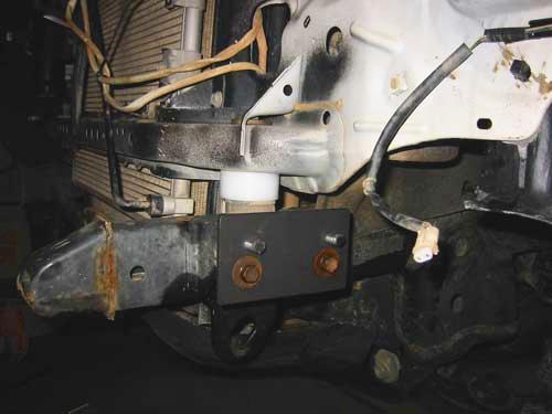
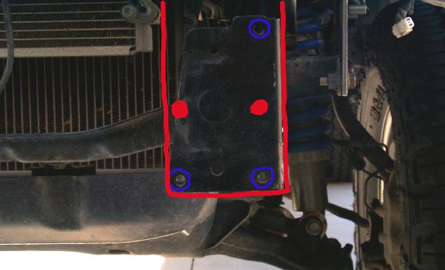
- Another option, that costs nothing, is pictured above (D), is to simply relocate the bracket on the back side of the front bumper to match the lift. At 1" (pictured on D above), you'll need to drill one new hole per side to raise the bumper. Typical for 2001-2002 4Runners:
- At 1.5", you may find enlarging the 2" offset holes may allow enough adjustment to fit the bumper for the body lift.
- At 2", one of the existing holes should line up for re-use.
- At 3", you may again need to drill one new hole per side
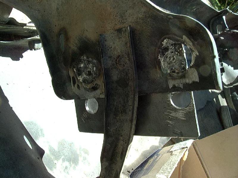
On the 2000 and later 4Runners and the 2001 and later Tacoma pickups, there may be a two piece front bumper, the outer cosmetic bumper that bolts to the frame as shown above and an inner bumper that spans the front frame rails. It is bolted to the front of the frame (see photo B above) and sits inside the outer bumper. In order to raise the outer bumper, something must be done to make it clear the inner bumper, since its effectively wrapped by the outer bumper.
Some options are:
- Notch out the bottom of the outer bumper so that it can be raised to match the body lift and bumper lift brackets.
- Flip the inner bumper upside down and end to end and remount it higher.
-
Re-drill new mounting holes in it, or weld it on higher) to raise it to
match the body lift (in above photo B, the stock holes are
highlighted in blue, the new holes are shown in red)
- Note, that at certain lift heights, you may not be able to get the inner bumper raised the exact height of the body lift, this is not critical. Raise it enough to fit and that is fine.
-
Have the inner bumper brackets cut off and re-welded with an offset at
a local shop.
- Or send us a sketch or photo and some dimensions of the bolt hole layout on the inner bumper frame attachment and we can try to design a bracket to lift that inner bumper up to match the lift.
- Remove the inner bumper, for increased ground clearance (approach angle) in off-road use.
Likewise, on the 2001-02 4Runners, the factory bumper bracket has an extension in the rear which holds the 2nd bolt, instead of being lined up horizontally as pictured above. In order to fit the bumper raising bracket, a new 1/2" hole needs to be drilled in the factory bumper bracket to line up with the hole in the lift bracket, then once attached, the factory bolts are used to attach the lift bracket to the frame using the two horizontally aligned holes. If the extension piece of the stock bracket is in the way, it can be trimmed off as needed. Other brackets that attach between the bumper and frame may also need to be modified as needed.
Note on drilling holes in steel:
If you need to drill a ~1/2" hole but only have a 3/8" drill (the most common household size chuck), you can find 1/2" drill bits with reduced shanks to allow using that bit on a 3/8" drill. Check your local hardware store. For example, the Irwin #73832 bit is set up like this and can be purchased for around $5.00. To drill holes in steel with a smaller drill, you may find it easier to work up from a smaller to larger bit instead of just starting with the 1/2" bit. An alternative to conventional bits is a stepped drill bit, or Unibit. The Irwin 10231 bit is a good bit, able to drill its own starter hole then enlarges the hole in steps up to 1/2" dia. and fits a smaller household drill. Use a variable speed drill, if possible, and use a slower speed as the bit size increases. Also, use some sort of cutting oil to keep from overheating and softening the drill bit.
[Return to the top of this page]4th Generation 4Runner and FJ Cruiser and '05+ Tacoma pickup:
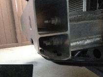
No bumper brackets are possible on the 4th gen 4Runner, FJ Cruiser and 2005+ Tacoma pickups for mild body lifts. The stock front bumper attaches to studs on the front of the frame. The studs are usually arranged in one of two ways that we have heard of to date.
First is aligned vertically and spaced about 1 - 1/4" (~30mm) on center and it is a simple matter to raise the bumper up that far by simply placing the bumper one set of holes upward:
 O
   30mm
 O
   30mm
 O
For a 1" body lift, the bumper will sit higher than it used to, although it may also contact the body above and hinder re-installing it, so it can be left as-is. For a 1.5" lift, it'll be a little lower than before (relative to the body), but the offset is not evident. A 1.25" lift will result in the best fit. (if anyone has some photos of a relocated front bumper, we would love to have a copy to post here for others to see - we forgot to take a picture of that when we installed out first 4th gen 4Runner kit).
Certain models will have a heavy metal cross member behind the outer (cosmetic) front (and rear) bumper. At lifts above 1", the bottom of the cosmetic bumper may need to be trimmed to fit around the cross member. If so, you can leave the inner cross member where it is and just move the outer cosmetic bumper up.
Some later model (2014?) Tacoma pickups, there still are three studs on each side of the frame, but they are arranged in an "L" configuration, as pictured below:
 |
| L-shaped bumper mounting studs |
Be sure to check your truck and see which type of bumper mounting you have before you decide to order and install a body lift. Many customers opt to use an aftermarket front bumper that can be built to accomodate a given body lift height.
Since the studs are a part of the frame and they stick out forward into the bumper structure, there is no way to make an easy bolt-on front bumper bracket. Options you might have are to remove the existing studs and then weld them on higher up the frame. Or you might be able to notch out the back side of the front bumper then fabricate and attach a filler plate with new mounting holes drilled to match the lift. Or you might be able to remove the cross member and drill new holes as far below the existing holes as possible and then remount as high as you can get it. Of course an aftermarket front bumper custom made to match the lift is also an option as is doing nothing and leaving the bumper in the stock location. If leaving the bumper as-is, you might notice a gap between it and the body. Sometimes the gap is made more visible since it may not be fully painted (i.e. just primer), so painting it to match the body or perhaps a flat black to blend in with the shadow might help minimize its appearance. Likewise, some folks have installed a thin strip of metal, plastic or sheet rubber to simply fill in the space and make it look like that is the way it is supposed to be. We did this on our '85 4Runner which has an aftermarket front bumper that did not really fit the vehicle that well. We just fashioned a sheet metal filler for that body-bumper gap.
Best to have made the decision of what you want to do with the bumpers before ordering and installing a body lift instead of afterwards.
[Return to the top of this page]Rear Bumper Relocation:
- So why no rear bumper bracket on some vehicles?
- On the Toyota 4Runners and FJ Cruiser models, the rear bumper is typically attached to the body, so it raises automatically with the body lift.
On the Toyota pickups and Tacomas, the bumpers are usually frame mounted. However, lifting the bumper is often not required, in that the body will clear the bumper, unlike the front bumper. In most cases, if it is desired to raise the rear bumper, there is usually enough extra metal in the bracket to allow new holes to be re-drilled, again unlike the front bumper. Therefore, a rear bumper bracket is not part of this body lift kit.
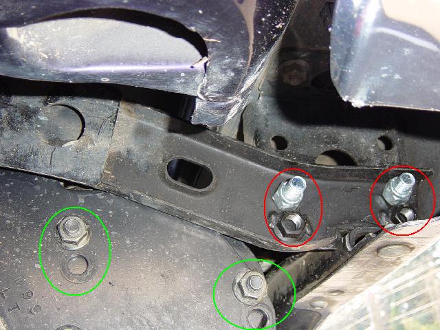
On the Toyota Tacoma pickup, the factory bumper brackets bolt to the frame and attach to the bumper, dropping it ~1.5" below the frame. There is enough extra metal in the factory brackets to allow re-drilling the bumper mounting holes up 1" higher to account for a 1" body lift. Shown above is a 1" relocated rear bumper bracket (modifications circled in RED) and tow hitch bracket (modifications circled in GREEN). New holes are drilled 1" higher than the stock locations in the bumper bracket (easiest to drill since it can be removed) to raise the bumper and tow hitch (if present). Some notching of the bumper bracket can be seen to let it fit inside the bumper itself. You can re-use the stock bumper bolts and install the 4 M12-1.25 nuts from kit RB, since the factory nuts are welded to the bracket that comes off the frame. You can also use new 1/2" or equiv. bolts and nuts if you wish.
For taller lifts on the Tacoma pickup rear bumpers, the stock bumper brackets can be swapped side to side, flipping them upside down. This nets a ~3" lift (i.e. 1.5" above the frame) if using the stock mounting holes. However, by using the above hardware kit (RB), and redrilling holes offset 1" from stock (in this case lower), the bumper can be reattached 2" higher quite easily (i.e. 3" - 1" = 2" of lift). With the brackets flipped over, the mounting holes no longer leave the bumper perfectly level, so its best to get one bolt in first, set the bumper to level and then mark and drill for the second hole.
In all the above options, some trimming and/or grinding of the various brackets may be required for a proper fit. This can be seen in the lower right corner of the picture above, the bottom of the factory bracket is notched to clear the reinforcement brace inside the bumper. With any amount of lift (1"-3") you will have to do some cutting/grinding/drilling to get the bumper raised to the desired height and sitting level and clear of the tailgate. The bolt holes are ~1/2" in diameter.
A benefit of modifying the OEM brackets like this is that if in the future, if you decide to change or remve the body lift, the original bumper brackets are still there. If we supplied a complex and expensive replacement bracket for the rear bumper and the original brackets were tossed. You would be out of luck if at some point you decided to lower the truck back to stock height.
[Return to the top of this page]Bed Spacers:
Pickup beds (as well as cargo areas on some full bodied vehicles like 4Runners) are supported both by bolts through the frame brackets and bed as well as by the simple physical contact of the bed cross members resting on the frame. When a body (and bed) lift is installed, these physical contact points are lost. Bed spacers can be used to fill the gap left by the lift. They should be installed directly to the frame, underneath where the bed cross member(s) would have otherwise made contact. The bed spacer then provides support to the center of the bed, somewhat like an overload leaf on a spring. If the bed is loaded or otherwise flexes far enough to make contact with the bed spacer, the spacer will carry the additional load or stop the flexing of the bed. Without the spacer, the center of the bed can flex/sag farther that it would with the spacer installed. Now, if your pickup carries at most a cooler and a couple of folding chairs, then you probably do not need this additional overload support. Likewise, if you sometimes carry rigid cargo like lumber or even dirt bikes where the load can support itself or only rests on the front and back of the bed, you can probably get by without bed spacers. But, if you routinely carry heavy, bulk cargo like sod, bricks, dirt, gravel, etc. where there is unsupported dead weight in the center of the bed, then bed spacers are a good idea.
The spacers are designed to be screwed or welded in place. To bolt them on, self tapping screw are supplied, mark the location of the mounting hole, pre-drill a 1/8" - 3/16" pilot hole then use a hex driver or wrench to screw them to the frame rail. Tighten the screw until it is snug with the spacer and frame. Do not over tighten or you risk stripping out the threads. Feel free to apply a bead of adhesive/sealant between the spacer and the frame to hold it in place and keep it from working loose and rattling. And of course, if you have access to a welder, the bed spacers can be welded to the frame. The easiest way is to just weld the spacer bracket to the frame through the drilled hole.
A: 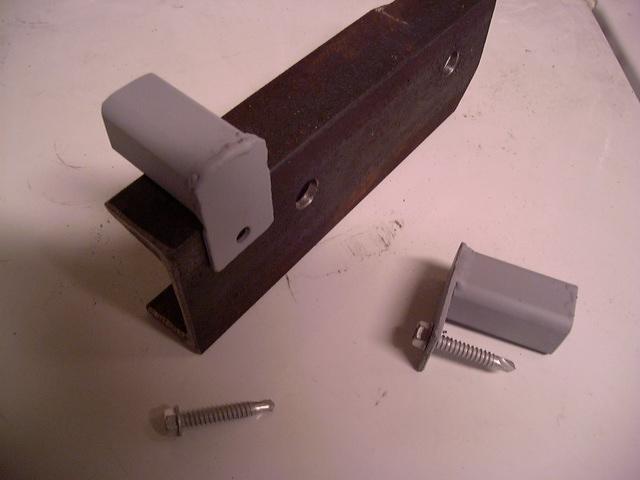 B:
B: 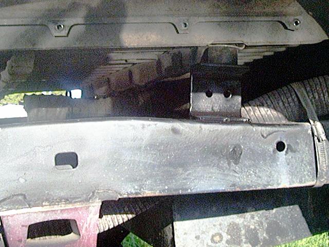
Picture A shows mounting a 1" bed spacer on a frame rail with the provided self-tapping bolts. Picture B shows a 3" bed spacer installed on a 1st generation 4Runner (this one is welded in place, but bolt-on versions are available), directly under the rubber bushing that originally sat on the frame rail. Also available (but not pictured) are 1.5" and 2" bed spacers; the spacer height should match the body lift height.
[Return to the top of this page]Radiator Relocation:
- Early model Toyota radiators
- Later model Toyota radiators
- Other radiators
- Here's a 3D CAD file you can use to make your own radiator brackets.
Note that it is not critical to have the radiator dropped to *exactly* match the body lift height. Two factors are involved:
-
One is that alignment of the fan shroud (mounted on the radiator which
in turn is mounted on the body) and the fan (which is usually mounted
on the engine which in turn is mounted on the frame).
- Usually there is about an inch of clearance around the fan blades, so as long as the fan clears the shroud, it should be fine.
- On some engines, the radiator fan sits back far enough to clear the shroud, so interference is not a problem.
- Be sure to account for engine flexing on the motor mounts under load when checking fan/shroud clearance.
- If you have an electric radiator fan, such as a Flex-A-Lite, you don't have to worry, as the fan is attached to the radiator.
- If you plan to raise the engine/drive train with motor mount spacers, then this will align the fan to the radiator.
-
The other is the radiator hoses that connect the engine to the
radiator.
- There is often enough flex in the hoses to allow for a few inches of offset and/or the hoses are bent in such a manner to allow reconfiguring them for the offset.
- If you plan to raise the engine/drive train with motor mount spacers, then this will align engine to the radiator.
As long as the fan does not hit the shroud and the radiator hoses are not kinked, radiator relocation may not be needed. Optimum cooling efficiency is achieved when the fan is centered in the shroud. A recent test in 4x4 and Offroad magazine showed a few percent drop in cooling efficiency without a fan shroud. If you drive in a hot climate with A/C on and tow a trailer, you may need every percent of cooling efficiency you can get.
So what you decide to do (or not do) to the radiator is up to you. For example you may have a 1" body lift and can relocate the radiator 3/4" by drilling new holes in the flange, that would probably work fine. Or if you have a 3" lift and can drop the radiator 2" with some existing holes, that too may work fine. It is not like there are "radiator police" that are going to stop and check your fan position. Bottom line is if it works for you, that is all that matters.
Below are some ideas on how you might choose to deal with this aspect of a body lift...
Early model Toyota radiators:
In Toyota trucks through the 1995 models, the radiator is attached to the front of the body, usually by 4 bolts, while the engine (and thus the fan) is attached to the frame. The radiator has a plastic shroud attached to it that encloses the fan to improve its efficiency. The lower half of the radiator fan shroud usually has a removable section that allows the shroud to be removed for service. When the body is lifted, the radiator, too is lifted in relation to the engine and fan.
Depending on how much clearance there is between the fan and shroud, the fan may hit the shroud due to lifting the body. If the fan sits back far enough from the radiator, it may miss the shroud altogether. If you look at picture #1, below, you'll see where the interference will happen. Alternately, it may be possible to simply remove the lower part of the shroud (see: picture #2) to allow the fan to spin freely (that piece is often missing) as you can see in picture #3, below. Ideally, the fan should be centered within shroud for maximum cooling efficiency, but in a well functioning system, cooling is probably adequate with the fan offset 1" from center.
1
2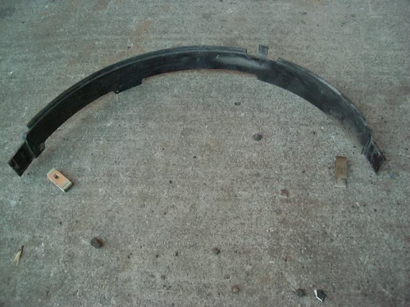
3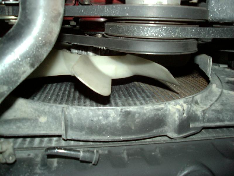
If the above steps do not correct the fan/shroud interference problem, then it may be necessary to relocate either the shroud or the entire radiator. That's when the optional radiator brackets are used. A typical Toyota radiator is shown in picture #4. below. You can see the mounting flange and the elongated holes that are used to mount it to the support bracket on the front of the engine bay. One might expect to simply drill new holes above the existing holes to offset the body lift. Unfortunately, there is often no metal available where the hole should be to allow this. In fact, on the pictured radiator, you should be able to see the remnants of the partial holes that were drilled through the flange and relocating bracket. One option is to simply redrill the holes as high up as possible (say 3/4") and go from there.
To solve this problem, the relocating bracket has studs that mount to the existing holes in the radiator flange and then has mounting holes spaced above the stock holes to allow relocation.
4
5
NOTES:
- It may be necessary to partially drill or cut away part of the radiator flange to allow passage of the stock mounting bolts.
- If you will be installing the relocating bracket, the best approach is to remove the fan shroud, drain and remove the radiator and do the work out of the vehicle, see instructions, below:
INSTRUCTIONS:
- Remove the fan lower fan shroud and the main fan shroud
- Remove the skid plate under the radiator
-
Drain the radiator and remove the upper and lower radiator hoses
- It may be possible to avoid this step if you are careful and can support the radiator in-place
- If your coolant is fresh, you can capture it in a clean container and use it to refill the system afterwards
- Install the bracket by inserting the bracket to the front side of the radiator with the studs projecting through the stock mounting holes; install a washer and nut on each stud to hold the bracket in place
-
It may be necessary to drill out the existing radiator flange if it
obscures the new mounting holes in the bracket
- Torque the nuts on the bracket studs to 10 ft.lbs.
- Install the radiator using the stock bolts through the new holes
- Install the fan shroud, spin your cooling fan by hand to check the clearances
- Reattach the hoses and refill the radiator with coolant
- Run the engine up to normal temperature, check for leaks, and if needed top off the coolant after the system cools off
Since every make and model radiator is a bit different, the best advice is to measure what you have in your vehicle, ahead of time. If there is at least enough clearance to allow for the body lift, you are set, if not, can the shroud be modified? If not, can the radiator be lowered? You may be able to get away with mounting the radiator 1/2" or even 3/4" lower, making use of the existing flange metal. Another option that works quite well is to pop-rivet a strip of 1/8"x1" steel or aluminum flat bar to the radiator flange and then simply drill new mounting holes wherever you want.
Later model Toyota radiators:
Of course the above options apply to the later model Toyota radiators (Tacoma and 3rd/4th generation 4Runner and FJ Cruiser). In addition, the options below may also be applied. Only one of the listed options need to be done, not all of them. You are free to choose the technique that best suits your needs. There is no "best" option, use the one you feel most comfortable with.
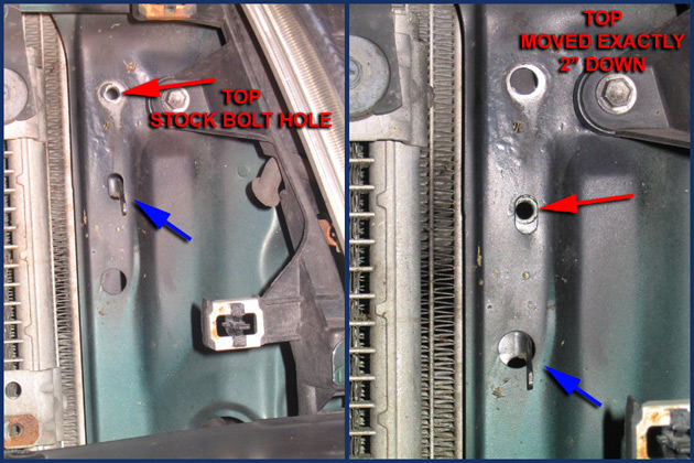 |
Typical factory bolt hole locations |
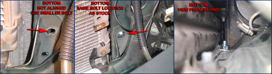 |
| Radiator re-mounted 2" lower |
On the Tacoma pickups and 3rd/4th Gen 4Runners and FJ Cruisers, the radiator flange has threaded mounting holes on it, and is attached with bolts that pass through the sheet metal behind the grill. To relocate this radiator, you can drill 4 new mounting holes in the sheet metal then re-attach the radiator using the stock fasteners in the new holes. Note that some models may have existing holes located approx. 2" below the stock holes, in this case no drilling is required. See the above photos for details. Upper pair of holes can use the stock bolts. For the lower holes, you may need to pick up some smaller bolts and larger washers to use the larger holes for the bottom radiator holes.
IMPORTANT:
Be sure to check the back side of the radiator and where it is going to sit after relocation to make sure there are no metal tabs or projections sticking out that will interfere with the radiator in it's new location. If any tabs are in the way, bend the over out of the way to allow the radiator to sit flush to the core support.
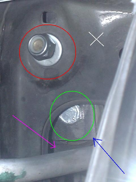 |
White X Magenta Arrow Blue Arrow Red Circle Green Circle |
Vehicle front/core support The radiator flange One (of 4) radiator drop brackets Threaded stud/nut from the radiator bracket Screw through bracket into radiator flange |
| Radiator Bracket Installed | Legend | Description |
A special drop bracket kit is available for the Tacomas and 3rd/4th generation 4Runners and FJ Cruisers that is bolted to the front side of the radiator mounting flange with (supplied) flat-headed metric allen screws through one of the holes (hex head screw shown at the bottom of the photo above). Then the stud on the bracket is slipped through the stock mounting holes in the front core support and fastened with a nut (supplied - at the top of the photo above). The bracket is designed to allow the radiator brackets to be installed with the radiator in place. This is done by maneuvering the radiator around such the allen head screw (a hex head screw pictured) can be installed through the bracket and into the nut in the radiator flange via existing access holes in the core support. You can also use the original hex head bolts if you wish, they may be easier to install using a ratchet wrench but will push the radiator back a bit farther due to the height of the hex heads.
Once all 4 brackets are installed, lined up and tightened, the bracket studs can be inserted in the core support holes. The brackets can also be installed by draining and removing the radiator.
NOTE: You'll end up with left over hardware if using our brackets.
Other Radiators:
On the Toyota Landcruiser FJ-60/2 vehicles, the radiator is mounted on rubber bushings attached to a bracket on the core support. If relocation is desired, it is possible to reconfigure the bushings and mounting to lower the radiator. No brackets are needed. Shown below if the stock setup, you can just invert that stock bracket/bushing to alter the height of the radiator.
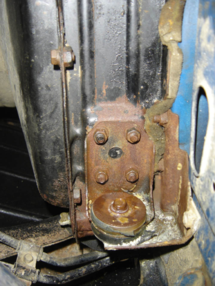 |
| FJ-60 Radiator Modification |
Another option is to cut the metal fan shroud in half across the "equator" then separate the two halves to account for the lift. Then insert a piece of sheet metal to fill the gap if desired, pop rivet, screw, or spot weld the metal piece in place.
On the Toyota Landcruiser FJ-80 vehicle, there is sufficient metal in the stock radiator bracket to allow redrilling mounting holes for a 1" body lift. Above that height and a drop bracket may be required. See the FJ-80 body lift install thread for details.
[Return to the top of this page]Shifter Modifications - (if needed):
Different vehicles have different types of shift linkages and the changes needed depend on the type of linkage, the amount of lift and the year and make of the vehicle. There are no hard and fast rules as to the linkage adjustment, some folks have had no issues with a 2" or higher lift, others have literally had shifter binding at just over 1/4" of lift. So below are some examples of various types of problems you may encounter and some ways to correct them:
Manual Transmissions and Direct Shifted Transfer Cases
Toyota Automatic Transmissions; '95 and earlier
Toyota Automatic Transmissions; '95.5 and later
[Return to the top of this page]Manual Transmissions and Transfer Cases:
Due to variations in body and frame, different model years, you may or may not experience shift lever interference with a body lift. Shown below are various shifter and boot configurations. It is not possible to picture each and every possible combination, so representative samples are shown. Also, it is not possible to show every possible problem and every possible solution, so typical problems and solutions will be shown. It will be the responsibility of the installer of the kit to ascertain the cause of any shifting problem and then decide how to correct it. You won't have to do all of these remedies, just the one that applies to the issue you've run into on your vehicle.
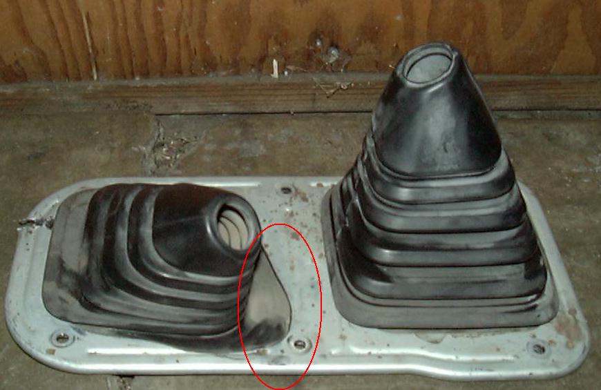
Here is a case where the stock transfer case shift lever would push the rubber shift boot against the lip of the metal cover plate in 4-LO position (shifter to the right and forward). On smooth terrain, this was not even noticeable, but in uneven terrain, the relative motion of the drive train and body, was enough to kick the transfer case into neutral. The fix is fairly easy, simply cut away some of sheet metal around where the shift lever was in 4-LO and this cured the problem. In the picture to the left, you can see the section cut out of the cover plate (outlined in the red oval). Normally the boot entirely covers the hole in the plate, but by enlarging the existing hole with a sheet metal nibbler and/or tin snips, there is now a larger open space for the shifter to move. This cover plate is not visible once either the carper or shift console is reinstalled, so it doesn't have to be very pretty. Another option is to cut out the whole web of sheet metal between the two openings, essentially converting an "8" into a "0".
In any event, you should thoroughly check the shifters in all possible combinations to ensure no binding is present. Also, it is a good idea to go out for a good off-road test drive to shake out the system.
Another option to cutting the cover plate is to bend the shift levers so they avoid the interference. This can be done with a long pipe over the shift lever end to bend it cold. Heating is another option but the shift levers have some plastic material so you need to be careful to not melt/burn that.
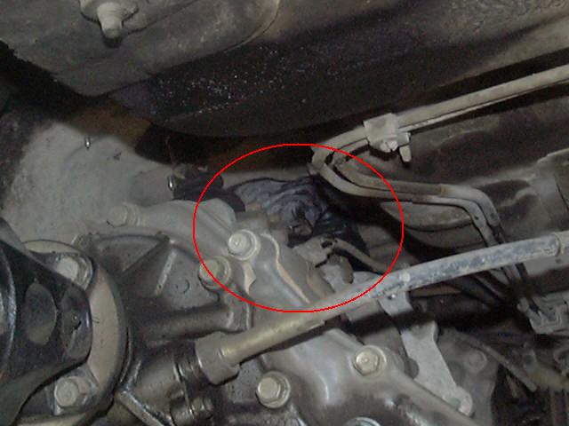 |
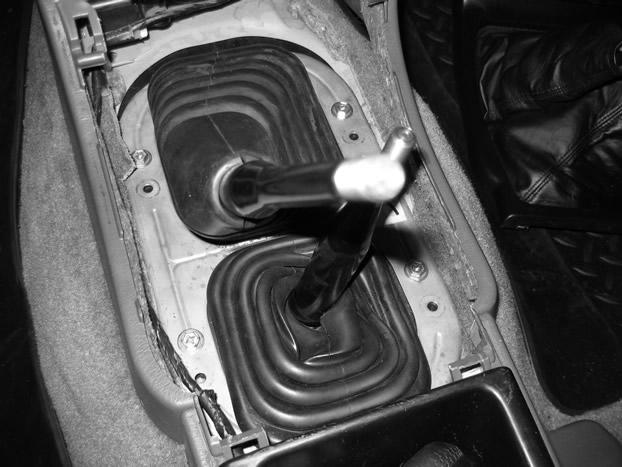 |
| A: Inverted Shifter Boot | B: Relocated Base Plate |
Alternately, you can try inverting the inner heavy rubber boot (image "A" above; either by pulling it off, flipping it upside down and re-installing it, or by pushing the cone of the boot down to turn it inside out). This will help in cases where the boot itself is pulling on the shift lever, by placing the tip of the boot down, it can flex farther without pulling so hard on the lever. Basically, you want the pointy end of the boot to be as low as possible. This is a good option in the taller 2"-3" body lifts. Another variation on this "fix" is to mount the shifter boot below the floor and possibly beneath a spacer. By tracing the outline of the shifter boots on a piece of exterior plywood and cutting out a spacer, place it below the floor. Probably easiest to install if you drive some carriage bolts in from below to serve as studs or put some clip nuts on the boot base and catch them with longer screws through from above.
Another option is to move the shifter boot base plate forward or backward by redrilling the mounting holes (image "B" above). This can be a help if you find the hole for the shifter is not exactly centered over the transmission or t-case shifter. For example, if the "even-number" gears have trouble staying in gear, this means that the shifter is binding when it is shifted towards the back of it's throw. Moving the shifter base back 1/2" to 1" as needed to re-center it may help. Likewise, if the "odd-number" gears have trouble, try moving the base plate forward. Click on the thumbnail above to see this in detail. Notice how the screws are sitting forward of the original holes. New holes were drilled into the sheet metal forward of the ooriginal holes, effectively mooving the whole boot assembly back. This simple modification solved the problem of being unable to shift into 2nd or 4th gear. An easy way to determine how far to move the holes is to leave the screws out and then shift into various gears and see where the base plate wants to sit in order to get all gear positions working.
You can also bend the shifter if it only rubs in one particular gear. For example if the t-case lever rubs in 4LO, pull the lever out and bend it back a little, so that its not so far forward in 4LO. It is best to bend the lever at the bottom, below the thick section. Also, DO NOT heat the shifter in order to bend it, this is because the shifter is a 2-piece construction, with the thin lower rod inserted into the thick upper portion and held in place with a thermosetting plastic. If heated, the plastic will melt and possibly loosen. Best bending method is to clamp the shifter in a vise, then slip a length of pipe over the end of the shaft and bend it slowly, by hand, in the direction desired. It is a good idea to bend a little, then check the fit and bend a little more, rather than trying to get it all in one shot.
But there is another easy option that not only solves this problem, but also makes the transfer case shifting better:
[Return to the top of this page]Weld-in Shift Lever Extension:
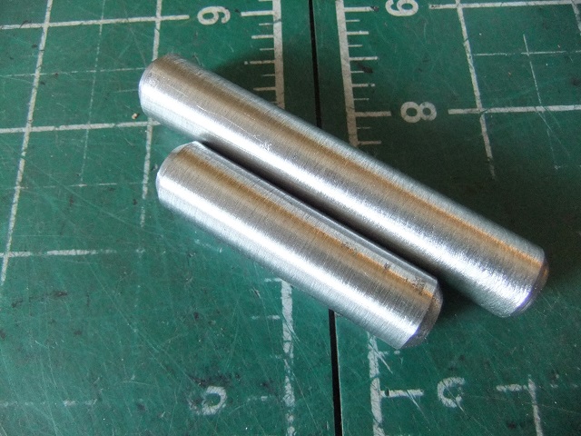
Of course, you could always do something like the Performance Accessories body lift kit provides for shifter extensions. Basically 2 pieces of 1/2" steel rod, which you are supposed to use to extend the shift levers with. The instructions say to remove the shift lever from the truck, cut it in two near the base (below the large upper section) then weld in the extension piece, while maintaining the proper shift lever alignment (top-bottom) and being careful not to melt the plastic sound dampening material that bonds the lower shift rod to the upper portion, then re-install the lengthened shifter into the gear box and bend as needed to get proper shifting movement. If you need some rod lengths to weld into your shifters, click here to purchase weld-on extensions.
[Return to the top of this page]Screw-on Shift Lever Extension:
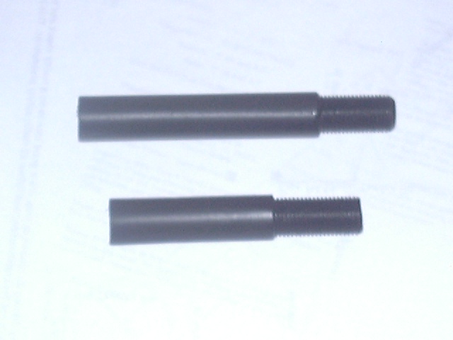 |
 |
| 2" and 3" Shift Lever Extensions | Shift Lever Extension Installed |
If you simply want to make the shift levers longer, a screw-on extension is available that attaches to the end of the shift lever. Installation is easy, unscrew the knob on the shift lever you wish to extend, screw on the extension (2" or 3" additional length), then screw on the knob to the end of the extension. For a more secure installation, you can apply a drop of thread locking compound to the threads on the end of the shifter to secure it in place. The screw-on extensions are made to match the thread size and pitch of the existing shifter knob. Currently, the shift lever extensions are available in M12-1.25 metric extra fine thread pitch for Toyota vehicles. And it is for "simple" shift knob shifters, where there is simply a knob screwed onto the end of the shifter. If you have a knob that is not screwed on or one with buttons and/or switches on it, then this style extension will probably not work directly.
[Return to the top of this page]Toyota Automatic Transmissions; '95 and earlier:
The A/T shift linkage on the Toyota vehicles (up through 1995 pickup and 4Runner models) consists of two main parts, the transmission shift lever and the transfer case shift lever. The transmission lever is adjustable and can handle up to a 3" body lift with simple adjustments. The 4WD (or transfer case) shifter, on the other hand will only work up to about a 1" body lift without modifications. 4Crawler Offroad now offers a bracket that lifts the transfer case shift lever up 2" so that body lifts in the 2" to 3" range can now be done on A/T equipped Toyota 4WD vehicles. Below 2" body lift, there is typically enough adjustment range in the factory linkage to allow the linkage to accommodate the lift. For lower height lifts, skip the A/T bracket installation steps and go to the A/T linkage adjustment steps below.
- Note:
- Its important to remove the bolts holding the shifter base to the floor before lifting the vehicle more than 1", or at least keep an eye on the linkage to make sure its not binding or hanging up on something while lifting.
A/T Bracket Installation:
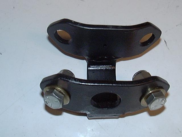 |
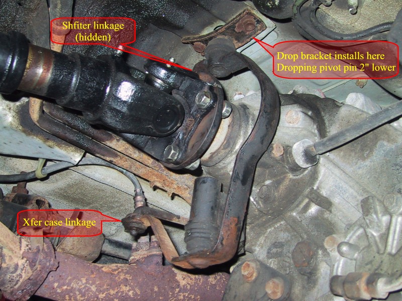 |
| A. A/T Shift Lever Bracket | B. Bracket Install Location |
 |
 |
| C. Shift Linkage Adjustment | D. 3" A/T Bracket, Installed |
Image A shows the bracket for the transfer case shifter. Image B shows where the transfer case shift lever is attached to the underside of the floor of the vehicle. It is a simple matter to unbolt the lever, bolt in the extension bracket and then bolt the lever to the bottom of the bracket to restore the original body-transfer case alignment, as shown in image D (circled in red). Also pictured in Image D, is the additional linkage bracket for the 3" lift installed (circled in green). It is used to raise the attachment point for the transmission shift linkage to allow for more adjustment room (see below) in the linkage and to keep the angles closer to stock for better operation. Basically this is needed with the 3" lifts only and is used to make up for a limited amount of adjustability in the stock linkage. There is a single bolt holding the linkage off the shifter to the linkage off the transmission and that bolt is into a slotted hole. You can separate those two links and insert the square steel bracket in between the two. Bolt the bracket to the existing bolt in the single, larger bolt hole and then use the two smaller bolts to bolt the bracket to the slotted hole in the mating linkage. If needed, you can turn the bracket end for end to gain more adjustment range. The two bolts in the slotted hole are used to make small front-back adjustments and also prevent this bracket from twisting under shifting forces. Orientation of the brackets is not terribly important, install them the way they fit the best. You may find it necessary to bend the center part of the U-shaped bracket to better fit the shift linkage.
A/T Linkage Adjustment:
The transmission shift linkage may be easily adjusted (see Image C, above) to accommodate the lift by following the factory shift lever adjustment procedure:
- Loosen the nut on the shift linkage
- Push the manual lever fully rearward
- Return the lever 2 notches to the NEUTRAL position
- Set the shift selector to "N"
- While holding the selector lever lightly toward the "R" range side, tighten the shift linkage nut
Toyota Automatic Transmissions; '95.5 and later:
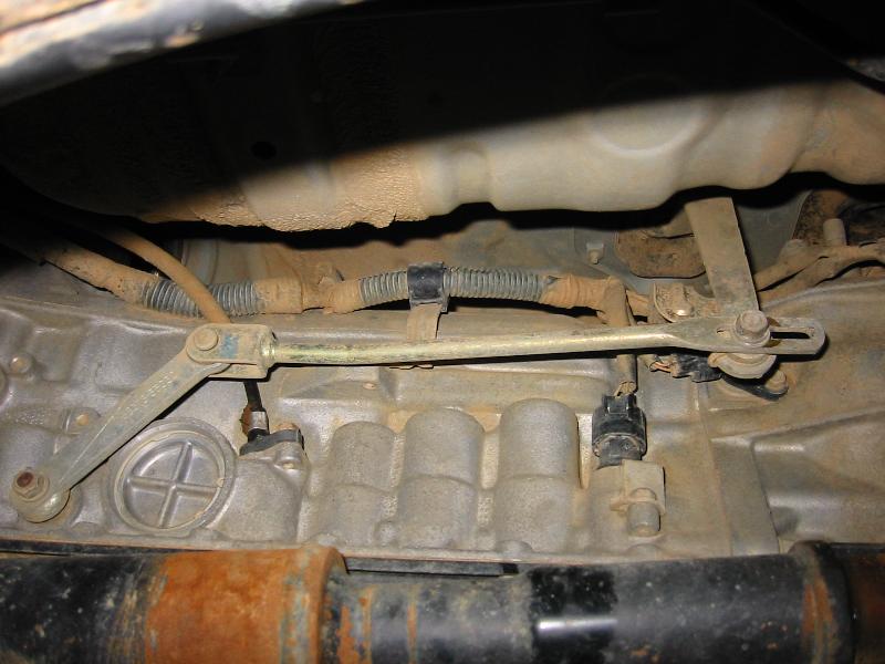
On the 1995.5 and later Tacoma and 3rd Gen 4Runner, the A/T shift linkage is more "body lift friendly". It is a simpler linkage and easier to adjust. In the image below, you can see the shift linkage and the adjustment needed for a 1" body lift. The general adjustment technique is the same as for the earlier automatics, above, except no brackets are needed, as the linkage has sufficient adjustment range for up to a 3" body lift. Basically you want to make the gear indicator under the shifter point to the actual gear the transmission is in.
On the 2WD Tacoma pickups, you may have a cable operated shift linkage and all that needs to be done is to ensure there is enough slack in the cable for the lift. This may require re-routing the cable slightly.
[Return to the top of this page]Hoses, Wires, etc.:
Many hoses and wires cross the body-frame gap and may need to be adjusted any time the body is lifted off the frame. Examples include the gas tank (filler and vent hoses), radiator, power steering and brakes. Most of the time no adjustments will be required. Some times, you may need to loosen a hose clamp, and adjust the end of the hose to relieve the stress in the line. Brake hard lines typically are coiled where they pass from the body to the frame. These coils should handle the lift just fine, just check that the lines are not getting hung up or pinched. Hoses to the clutch slave cylinder should have enough slack for 1" - 2" of lift and at 3", you may need to carefully stretch the coils out to fit. Worst case is when you are installing the lift, since you'll have the body raised up higher than the final height.
If needed, gas tank filler (~1" dia.) and vent lines (~1/2" dia.) can be extended with lengths of fuel line tubing (not included in the kit). You'll need approx. 5" of each diameter tubing for each line extended, there is usually one filler and 1-3 vent lines that need extending. These hoses, if needed, should be readily available at any auto parts store. Other hoses may be attached to brackets, such as the gas tank filler neck on the Tacoma and 3rd Gen 4Runner. In this case, the retaining bolt can be removed, the bracket bent up to match the lift or add the optional filler spacer (GAS kit item) and longer bolt, then the bolt can be re-installed. You can also add additional washers to space the filler tube up higher. Just keep adding washers until the gas cap can screw in and out easily. Don't forget to reinstall the gas cap once everything is finished.
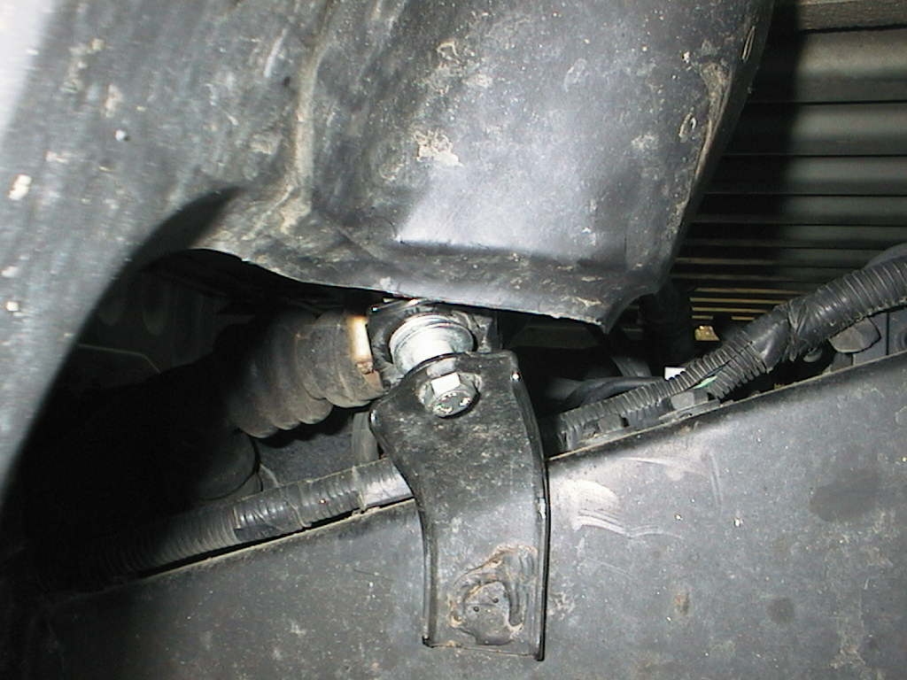
Wires and ground straps should be examined for tightness, while lifting. If wires are pulled tight, see if they are clamped at one end or the other. If so, either remove or relocate the clamp if possible. If ground straps are tight, see if one end or the other can be moved, if not, replace the strap with a longer part. Braided copper ground straps are available at most auto parts stores. On Tacoma and 3rd Gen 4Runner, the wires to the fuel tank level sender unit may need to be relocated or lengthened. Wiring is not included in the kit.
After installing a body lift, keep an eye out for new leaks from hoses that are pulled too tight, or for electrical problems that may be related to missing grounds or connectors that pulled apart. Examples may be turn signals that either do not flash or flash too fast, or gas gauge that doesn't not work (connector is usually on top of the gas tank w/ wires running up to the body), or 4WD or backup lights that do not come on, etc. Other issues that may arise are new noises. They may be present due to some component making contact with something else due to the lift. Examples are the steering column penetration in the firewall, the hole may need to be enlarged or the penetration plate relocated. You may also just be hearing a difference due to the additional space around the drive train. With more space, there may be a new resonance that was not present before. You may be able to apply some sound deadening material to quiet things down if needed. And don't forget about those tools you may have used for the install. We had one report of a strange clunking sound after installing a body lift. After the owner spent much time searching for the source, it turned out to be the factory bottle jack, that he had used to install the lift, that was not properly secured in the back of the truck. Once he strapped that back down properly, there was no more noise. Also, check the throttle cable, it may have been pulled tight by the lift, causing the throttle to open slightly, resulting in a fast idle. If found, re-adjust the throttle cable for normal operation.
Check if any of the white body lift blocks will be exposed to sunlight after installation. If so, it's a good idea to apply some black spray paint or a spray on rubberized undercoating to any exposed surfaces. This will prevent any degredation over time due to UV light exposure: - Information on UV exposure If you ordered our custom color / black lift blocks, they are good to go.
On 4th generation Toyota 4Runners with the XREAS suspension setup, there may be more extensive hose/wiring adjustments needed to deal with the XREAS compressor and shock setup. Everything can be adjusted for the lift, but will take some time and effort to properly handle everything. No additional brackets or hardware is available for this task.
[Return to the top of this page]Caveats and Pitfalls:
4Crawler Offroad can't begin to address all possible issues you might encounter while installing a body lift. Instead, you'll find described below some of the issues that have been encountered so that you'll have an idea of what issues you might run into and what can be done to solve them. Not everyone will encounter every issue:
- Damaged or missing hardware:
- It is not uncommon to run into rusted bolts or find nuts that won't come off of bolts. You may find one stuck fastener that can take as much time to deal with as the rest of the lift. That is why it is difficult to provide an exact time/difficulty estimate for the kit installation. In ny case, my 4Runner was missing one rear body mount all together, no bushings, washers, bolts, it was all gone. Also, the two front mounts were "fastened" with perhaps 1/4" bolts, badly bent and severely over-stressed. While this is probably unusual, things like this happen. You may not be able to re-use existing parts (if they are damaged or missing). Luckily, I was planning to replace all the mounts anyway, but you should check first. 4Crawler Offroad recommends replacing 1st generation (2-piece) rubber body mount bushings with new polyurethane ones. If interested, 4Crawler Offroad can supply poly bushing kits for many vehicles.
- Aftermarket front/rear bumpers:
-
Some may use the front body mount bolts as part of their mounting
system. For example, the dual tube SmittyBilt bumper bracket attaches
to the front body mount bolts in addition to the stock bumper mounting
bolts. This can cause a few problems. First, you may need to remove the
bumper to get enough clearance to install the body lift. Second, if the
bumper has been hit, it can bend and distort the front body mount
brackets making installation of new hardware more difficult. However,
the 4Crawler Offroad bumper bracket does work properly for the
SmittyBilt front bumpers.
- Other bumpers, such as the ARB and TJM, are designed so as to make lifting the bumper more difficult, but the do allow the body to be lifted independently. This is to say that a simple bolt on bracket to lift the bumper won't work. It may require drilling new mounting holes and/or cutting/welding the bumper brackets to accommodate the lift. However, there is always the option of leaving the bumper as-is with a small 1" gap.
- Rusted floor/bed panels:
- Especially near the body mount locations must be addressed before installing a body lift. The most common place to encounter rust is the 2nd body mount back from the front, in the front foot well. If your windshield leaks, water can pool on the floor and find its way to the lowest point, which is the pocket the body mount bolt sits in (beneath a plastic cap). If any of the body panels are rusted near the mount points, the added leverage of the body lift block can "punch" a hole right through the floor. This sort of damage should be fixed before installing a body lift.
- Automatic Transmission Shift Linkage:
- Apparently there is sufficient "play" in the stock '95 and earlier Toyota A/T shift linkage to accommodate a 1" body lift without adjustment. If this doesn't just work, it may be necessary to re-adjust the linkage to function at the new height. Consult the A/T shift linkage section for more details. In the '95.5 and later Toyota A/T linkage, both the transmission and transfer case shift linkages are adjustable for 1" - 2" lifts.
- Shift lever interference:
-
First the bad news; with a 1" lift, you may experience
interference with the shift levers and the now raised boots and shifter
console. Depending on the relative position of the transmission and
transfer case(s) to the floor panel, the size of the cutouts, the type
of shift boots and the angle and throw of the levers, they may be some
interference. It may or may not be apparent from a simple test of
shifting into all gear combinations. It may only show up in a
real-world off-road test where the frame and body are flexed.
- Now the good news; this is rather easy problem to correct. This is usually due to the metal cover plate that attaches the shift boots to the floor. It has cutouts for the shift levers to move in. By lifting the body, the pivot point of the levers effectively is lowered, which in turn causes the motion of the lever to increase at the level of the cover plate. It is usually a case of the boot getting pinched between the lever and the cover plate, preventing the lever from shifting completely into gear. By simply trimming away some metal from the cover plate at the point of interference will prevent the boot getting pinched and will most likely solve the problem. In more severe cases (usually seen at 2" and higher body lifts) the shift levers may need to be heated and bent, a step which puts those lifts beyond a "mild" lift. Another possible option is to install a "short-throw" shift lever, which raises the pivot of the shift lever 1" and reduces the length of the shift throw. A third option it to either rotate the shift lever 180 degrees, if possible, to see if it fits better, or it may be possible to bend the lever to better clear the interference.
- A 4th option is to install a short throw shift kit, raises the shift lever back up and makes the shift throw shorter and crisper to boot.
- Now the good news; this is rather easy problem to correct. This is usually due to the metal cover plate that attaches the shift boots to the floor. It has cutouts for the shift levers to move in. By lifting the body, the pivot point of the levers effectively is lowered, which in turn causes the motion of the lever to increase at the level of the cover plate. It is usually a case of the boot getting pinched between the lever and the cover plate, preventing the lever from shifting completely into gear. By simply trimming away some metal from the cover plate at the point of interference will prevent the boot getting pinched and will most likely solve the problem. In more severe cases (usually seen at 2" and higher body lifts) the shift levers may need to be heated and bent, a step which puts those lifts beyond a "mild" lift. Another possible option is to install a "short-throw" shift lever, which raises the pivot of the shift lever 1" and reduces the length of the shift throw. A third option it to either rotate the shift lever 180 degrees, if possible, to see if it fits better, or it may be possible to bend the lever to better clear the interference.
- Other Fitment Issues:
- 4Crawler Offroad doesn't have the resources to go test fit every combination of body lift kit on every possible year, make and model truck. 4Crawler Offroad has installed kits on representative vehicles and feel comfortable that they will fit as designed. With variations in specific vehicles, etc. 4Crawler Offroad can't guarantee all the parts will fit perfectly on any given vehicle. 4Crawler Offroad will be more than happy to work with you on resolving fitment issues as they come up. If something looks like it won't fit, please contact 4Crawler Offroad and together we can work on resolving the issue.
- Lift blocks exposed to daylight:
- If, after installing the body lift, you find some of the lift blocks exposed to sun light, you might want to spray the exposed surface with some black spray paint or rubberized undercoating spray to protect the UHMW material from UV light. Wipe the blocks down with isopropyl alcohol or acetone to remove any surface oil or grease before painting. With spray paint, you may want to rough up the surface a bit with some sand paper or abrasive pad. The undercoating spray should stick without sanding.
Lifts over 1":
While these instructions were written for a 1" body lift, they generally apply to taller lifts. The higher you go the more things there are to check and possibly correct. 4Crawler Offroad apologizes for the somewhat vague recommendations below, but its hard to give 100% yes/no answers on this subject. For example, one 4Runner may need transfer case shifter mods at a 1" body lift, while others may have no problems at a 2" lift. Some vehicles may need to do the radiator brackets at 1" lift because of a a thicker than stock radiator, others have done 1.5"-2" lifts without touching the radiator. For on-road or mild offroad use, having a slightly tight hose may not be a problem, in heavy offroad use, it may be. One way to think of it is as a probability, the higher you lift the body the higher the probability of running into one or more issues.
Here is a summary of items to check when doing taller body lifts:
-
At 2", the radiator probably should be relocated if you run the
stock fan and shroud.
- You will have to remove the radiator fan shroud prior to lifting the body
- An Electric radiator fan would not require any mods
- Unless a drive train lift is installed, then this will not be an issue.
-
On manual transmission Toyotas:
- At 2", the flexible hose to the clutch slave cylinder might be pulled a bit too tight and can easily be lengthened
-
At 3" it may need to be replaced or relocated:
- If a drive train lift is installed, then this will not be an issue
- A stock front brake hose is typically a few inches longer than the clutch hose and has the same fittings so makes a good replacement
- A flexible braided stainless steel clutch slave cylinder hose can be supplied if needed at a cost of $40.00
-
On early automatic transmission Toyotas:
- At 2" and above, the transfer case shift lever must be extended with the A/T bracket
- The shift lever itself is telescoping and may be adjusted as needed.
- Later model (1996+) Toyota automatic transmission linkages are more adjustable and typically work fine up to 3" body lift.
-
Gas filler and vent hoses may need some work:
-
May be able to loosen the hose clamps and slide the hose out a bit and
re-clamp it
- If too short, obtain a filler extension and insert it in the filler line.
- Although mine seemed to be OK at 3", before I raised the gas tank which is another option.
- Also a gas filler hose mount spacer (kit item: GAS) is available for the Tacoma pickups for $10.00
-
May be able to loosen the hose clamps and slide the hose out a bit and
re-clamp it
-
Power steering fluid reservoir hose may need adjustment.
- In the lifting process, the hose may get pulled enough to cause a leak, loosen the clamp, reseat the hose and re-clamp.
-
Steering shaft adjustments may need to be done.
- Loosening the top clamp on the splined section may relieve the stress in the rag joint
-
A 1-piece or vertical steering shaft will need to be extended:
- 1-piece shaft should be fine at 1"-2", but may need a 1" extension for a 3" lift
- A vertical shaft, like used on the Toyota rack and pinion setup will need to be extended at 1" and above
- You can also cut the shaft and weld in a section of tubing to span the gap
-
Check ground straps and other electrical connections between the frame
and body.
- Either replace it with a longer wire or relocate the mounting holes for the existing wire.
-
Check, double-check, then check again, do some mild wheeling and expect
to run into some problems, a lot easier to deal with back in your
driveway that out on the trail:
- I.e. don't do this the day before you head off for the Rubicon or Moab :-)
Torque Specifications:
Once you have all the body mount blocks in place, all the bolts inserted and loose after lowering the body/bed, and on pickups, the cab and bed are aligned, go ahead and torque down the fasteners. 4Crawler Offroad has been unable to find any "factory" torque specs for the body mount hardware. Going by the "Standard Bolt Tightening Torque - Appendix B, '85 Pickup/4Runner Factory Service Manual", 20 ft.lbs. seems appropriate for the size and grade of hardware used (3/8" or 10mm) and 30 ft.lbs. is good for the larger diameter hardware. In some shop manuals, Toyota lists a torque of approx. 34 ft.lbs. for the larger dia. (7/16", 12mm, 1/2") bed bolts on pickups and Tacomas as well on the 4th gen 4Runners, FJ Cruisers.
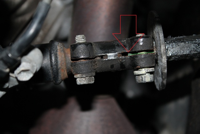 |
| Steering Shaft Slip Joint - typical |
Be sure to check that the steering shaft is still sufficiently engaged with the clamp, and re-torque the clamp bolt to factory specs, if it was loosened during the installation process. By sufficiently engaged, all you need to check is that the shaft, inside the clamp, extends at least past the middle of the clamping bolt. In the above image you can see the arrow pointing to the end if the highlighted steering shaft inside the clamp. Note that the shaft ends beyond the center of the clamping bolt and is thus fully secure. As long as you can see the end of the shaft beyond the center of the clamping bolt, that should be sufficient material for a solid clamp engagement.
IMPORTANT:
Be sure to re-check all fasteners after a few hundred miles (or kms) of driving. The lock nuts will prevent them from loosening up but things can shift and settle with road vibrations and cause a once tight bolt to loosen up. And some of the bolts, such as the Tacoma pickup bed bolts go into captive nuts (non-locking variety) that are inside the bed rails. These bolts should especially be checked for tightness after installing the lift. You simply want to ensure that all the components of the body mount are in contact with each other and there is no play in the system.
[Return to the top of this page]Difficulty and Time Estimate:
On the infamous "shade tree howler mechanic" banana scale, this project is rated at about 2-3 bananas.
- It can be done with one person, another pair of hands are helpful but not required, any more and you'll probably take longer.
-
Some means of lifting the body/bed is required, if you can jack up the
vehicle to change a tire, this will be a snap.
- Other than that, simple hand tools and perhaps a power drill and bit to enlarge holes in a few washers if needed are about it.
-
The entire installation should take about 2 hours per side, less if you
just jump in and do it, more if you stop to check things out, clean and
paint the frame, etc., then it can take longer.
- In any event, 4 hours is a typical installation time for the average person or shop.
In short, we like to say that if you can change a tire on your vehicle, you can probably install a body lift. Why? Both involve using a jack to lift up part of the vehicle and using a wrench or ratchet to loosen and tighten some nuts on some bolts (or studs). That is all a body lift installation is, a few more bolts, some of them a little bit hard to get to, but not a lot more than that.
If you have any suggestions or feedback to improve these instructions, please let us know. This is a living document, 4Crawler Offroad is constantly updating it based upon your feedback.
[Return to the top of this page]Body Lift Installation Instructions, v1.54
Visitor # since 28.AUG.2001
[Last updated: 10.January.2026]
Copyright © - 4Crawler Offroad 2000-2021 - All Rights Reserved The latest version of this document may be found at: - https:/www.4Crawler.com/4x4/ForSale/Docs/BodyLift_HowTo.shtml